This specification defines the features and syntax for Scalable
Vector Graphics (SVG) Version 2. SVG is a language based on XML for describing
two-dimensional vector and mixed vector/raster graphics. SVG content is stylable,
scalable to different display resolutions, and can be viewed stand-alone,
mixed with HTML content, or embedded using XML namespaces within other XML languages.
SVG also supports dynamic changes; script can be used to create interactive documents,
and animations can be performed using declarative animation features or by using script.
Status of This Document
This section describes the status of this document at the time of its
publication. Other documents may supersede this document. A list of current W3C
publications and the latest revision of this technical report can be found in
the W3C technical reports index at https://www.w3.org/TR/.
This document is the 14 September 2025 Editor’s Draft of SVG 2. This version of SVG
builds upon SVG 1.1 Second Edition
by improving the usability of the language and by adding new features commonly
requested by authors. The Changes appendix lists all
of the changes that have been made since SVG 1.1 Second Edition.
Comments on this Editor’s Draft are welcome.
Comments can be sent to www-svg@w3.org,
the public email list for issues related to vector graphics on the Web. This list is
archived and
senders must agree to have their message publicly archived from their
first posting. To subscribe send an email to
www-svg-request@w3.org with
the word subscribe in the subject line.
The specification includes a number of annotations that the Working Group is
using to record links to meeting minutes and resolutions where specific decisions
about SVG features have been made. Different coloring is also used to mark the
maturity of different sections of the specification:
a red background indicates a section that is either unchanged since SVG
1.1 (and which therefore still requires review and possible rewriting for
SVG 2), or a section that is new but still requires substantial work
a yellow background indicates a section from SVG 1.1 that has been reviewed
and rewritten if necessary, or a new section that is complete and ready
for the rest of the Working Group to review
a white background indicates a section, either from SVG 1.1 or new for
SVG 2, that has been reviewed by the Working Group and which is ready
for wider review
Publication as a Working Draft does not imply endorsement by the W3C Membership.
This is a draft document and may be updated, replaced or obsoleted by other documents
at any time. It is inappropriate to cite this document as other than work in progress.
A list of current W3C Recommendations and other technical documents can be found at
https://www.w3.org/TR/. W3C publications
may be updated, replaced, or obsoleted by other documents at any time.
All features in this specification depend upon implementation in browsers
or authoring tools. If a feature is not certain to be implemented, we define
that feature as "at risk". At-risk features will be removed from the current
specification, and may be included in future versions of the specification. If
an at-risk feature is particularly important to authors of SVG, those authors
are encouraged to give feedback to implementers regarding its priority. The
following features are at risk, and may be dropped during the CR period:
More than one ‘title’ or ‘desc’ to provide localisation
The SVG Working Group would like to thank the following people for
contributing to this specification with patches or by participating in discussions
that resulted in changes to the document:
David Dailey,
Eric Eastwood,
Jarek Foksa,
Daniel Holbert,
Paul LeBeau,
Robert Longson,
Henri Manson,
Ms2ger,
Kari Pihkala,
Philip Rogers,
David Zbarsky.
In addition, the SVG Working Group would like to acknowledge the
contributions of the editors and authors of the previous versions
of SVG – as much of the text in this document derives from these
earlier specifications – including:
Patrick Dengler, Microsoft Corporation (Version 1.1 Second Edition)
Jon Ferraiolo, ex Adobe Systems (Versions 1.0 and 1.1 First Edition; until 10 May 2006)
Anthony Grasso, ex Canon Inc. (Version 1.1 Second Edition)
Dean Jackson, ex W3C (Version 1.1 First Edition; until February 2007)
藤沢 淳 (FUJISAWA Jun), Canon Inc. (Version 1.1 First Edition)
Finally, the SVG Working Group would like to acknowledge the
great many people outside of the SVG Working Group who help with the
process of developing the SVG specifications. These people are too
numerous to list individually. They include but are not limited to
the early implementers of the SVG 1.0 and 1.1 languages (including
viewers, authoring tools, and server-side transcoders), developers of
SVG content, people who have contributed on the www-svg@w3.org and
svg-developers@yahoogroups.com email lists, other Working Groups at the
W3C, and the W3C Team. SVG 1.1 is truly a cooperative effort between
the SVG Working Group, the rest of the W3C, and the public and benefits
greatly from the pioneering work of early implementers and content
developers, feedback from the public, and help from the W3C team.
SVG is a language for describing two-dimensional graphics.
As a standalone format or when mixed with other XML, it uses the
XML syntax [xml].
SVG code used inside HTML documents uses the HTML syntax [HTML].
SVG allows for three types of graphic objects: vector graphic
shapes (e.g., paths consisting of straight lines and curves),
images and text. Graphical objects can be grouped, styled,
transformed and composited.
The feature set includes nested transformations, clipping
paths, alpha masks, filter effects and template objects.
SVG drawings can be interactive
and dynamic. Animations
can be defined and triggered
either declaratively (i.e., by embedding SVG animation elements
in SVG content) or via scripting.
Sophisticated applications of SVG are possible by use of a
supplemental scripting language which accesses
SVG Document Object Model (DOM), which
provides complete access to all elements, attributes and
properties. A rich set of event handlers
can be assigned to any SVG graphical object.
Within a web page, the same scripts can work on both HTML and SVG elements.
Scripting.
SVG is useful for rich graphical presentation of information, including a number
of accessibility features that, used correctly,
ensure the content can be used by the widest possible audience. But a direct
link to source data, where possible,
is helpful for many people to understand the content provided.
1.2. Compatibility with other standards efforts
SVG leverages and integrates with other W3C specifications
and standards efforts, as described in the following:
SVG can be integrated with HTML either by using SVG in HTML or by using HTML in SVG, in both cases either by inclusion or reference.
SVG is an application of XML and is compatible with XML 1.0 and with the Namespaces in XML specification. However, when SVG content is included in HTML document, the HTML syntax applies and may not be compatible with XML. See SVG Integration for details.
SVG content is styled with CSS. See Styling with CSS for details.
SVG includes a complete Document Object Model (DOM) and
extends DOM4.
The SVG DOM has a high level of compatibility and consistency
with the HTML DOM.
Additionally, the SVG DOM supports and
incorporates many of the facilities described in
the CSS object model and event handling
[dom-level-2-style]
[uievents].
SVG incorporates some features and approaches that are
part of SMIL 3, including
the ‘switch’ element and the ‘systemLanguage’
attribute.
SVG is compatible with W3C work on internationalization.
References (W3C and otherwise) include: [UNICODE]
and [charmod].
1.3. Relationship to previous versions of this standard
This edition of the SVG standard has been developed based on, and built upon, the 1.1 edition released in 2003.
An intermediate version of SVG - named Tiny 1.2 - was released
in 2008. However it did not receive wide acceptance and there have been very few implementations of its
enhanced feature set. However there are some 1.2 features that have been implemented by many SVG implementations and
those have been incorporated as part of this specification. But otherwise, the SVG Working Group consider version
Tiny 1.2 to be a deprecated branch of the SVG standard.
1.4. Normative Terminology
Within this specification, the key words "MUST", "MUST NOT",
"REQUIRED", "SHALL", "SHALL NOT", "SHOULD", "SHOULD NOT",
"RECOMMENDED", "MAY", and "OPTIONAL" are to be interpreted as
described in Key words for use in RFCs to Indicate Requirement Levels
[rfc2119].
However, for readability, these words do not appear in all
uppercase letters in this specification.
At times, this specification recommends good practice for
authors and user agents.
Chapter 2: Conformance Criteria
2.1. Overview
Graphics defined with SVG have many different applications.
As a result, not all software that uses SVG will have the same features.
Conformance to the SVG specification is therefore not a binary matter;
software may be conforming within a restricted feature set.
Furthermore, SVG is designed to be integrated into other types of documents;
depending on the type of integration, only a limited feature-set may be appropriate.
There are various ways that an SVG document fragment can be
referenced by or included in other documents and thereby
be processed by a user agent. SVG documents can also be viewed directly,
as the primary document.
Each different method by which an SVG document fragment
can be used implies a certain set of requirements on how the SVG document
fragment must be processed.
This chapter therefore defines a number of
processing modes
that encompass the different combinations of features
which may be enabled or disabled in the document.
In addition, it specifies normative requirements for which processing mode
must be used when SVG documents reference or embed other SVG documents.
The same set of processing modes may be used by reference in other specifications
to describe how SVG documents should be processed.
This document does not place normative requirements on
other specifications that can reference or include SVG documents, such as
HTML and various CSS specifications. The intention is for these other
specifications to normatively point to the appropriate processing mode
from this document.
This section defines a standard set of processing modes
for SVG documents. Each processing mode specifies whether certain high level
SVG features are enabled.
2.2.1. Features
The features that can be enabled or disabled depending
on the processing mode are as follows:
declarative animation
Declarative animation includes both the animation elements in SVG –
‘animate’, ‘animateMotion’,
‘animateTransform’ and ‘set’ – and CSS Transitions and Animations
(see the Animation appendix for details).
When declarative animations are disabled in an SVG document, any
animation elements or CSS Transitions or Animations must not be applied or run.
This is not the same as pausing the document's animated
state at 0s document time; if an animation is defined to begin at 0s,
it still will not be applied.
references to external resources
References to external resources are URLs references
or network access requests
made by markup, style properties, script or other Web platform features
used in the document, except for:
When external references are disabled in an SVG document, any attempt to
fetch a document through an external reference must instead be treated as
if a network error occurred and no data was received.
When external references are enabled,
user agents that support external file requests from the Internet
must adhere to the restrictions on cross-origin resource fetching,
as outlined in the Linking chapter.
script execution
Script execution is the execution of any SVG ‘script’ elements,
script found in event attributes (such as ‘onclick’ on
SVG elements), or any other script defined by other Web platform features
used in the document, such as any HTML ‘script’ elements.
When script execution is disabled in an SVG document, no script in the
document must be run.
interaction
Interaction refers to the delivery of DOM Events or the invocation of
any user agent specific UI behaviors such as text selection, focus changing,
link traversal, or animation or transition triggering that is done in
response to user input such as mouse or keyboard activity. When
interaction is disabled in an SVG document, any user input events that would
be targetted at the document or any elements within the document must have
no effect.
2.2.2. Dynamic interactive mode
This processing mode imposes no restrictions on any
feature of the SVG language.
Dynamic Interactive Features
script execution
yes
external references
yes
declarative animation
yes
interactivity
yes
2.2.3. Animated mode
This processing mode is intended for circumstances where
an SVG document is to be used as an animated image that is allowed
to resolve external references, but which is not intended to be used
as an interactive document.
Animated Features
script execution
no
external references
yes
declarative animation
yes
interactivity
no
2.2.4. Secure animated mode
This processing mode is intended for circumstances where
an SVG document is to be used as an animated image that is not allowed
to resolve external references, and which is not intended to be used
as an interactive document. This mode might be used where image support
has traditionally been limited to raster images (such as JPEG, PNG and
GIF).
Secure Animated Features
script execution
no
external references
no
declarative animation
yes
interactivity
no
2.2.5. Static mode
This processing mode is intended for circumstances where
an SVG document is to be used as a non-animated image that is allowed
to resolve external references, but which is not intended to be used
as an interactive document.
For example,
an SVG viewer that processes graphics for inclusion in print documents
would likely use static mode.
Static Features
script execution
no
external references
yes
declarative animation
no
interactivity
no
2.2.6. Secure static mode
This processing mode is intended for circumstances where
an SVG document is to be used as a non-animated image that is not allowed
to resolve external references, and which is not intended to be used
as an interactive document. This mode might be used where image support
has traditionally been limited to non-animated raster images (such as JPEG
and PNG.)
Secure Static Features
script execution
no
external references
no
declarative animation
no
interactivity
no
2.3. Processing modes for SVG sub-resource documents
When an SVG document is viewed directly,
it is expected to be displayed using the most comprehensive
processing mode supported by the user agent.
However, when an SVG is processed
as a sub-resource or embedded document,
the following restrictions must apply:
The same processing modes are expected to be used
for other cases where SVG is used in place of a raster image,
such as an HTML ‘img’ element or
in any CSS property that takes an
<image> data type.
This is consistent with HTML's requirement
that image sources must reference
"a non-interactive, optionally animated, image resource that is neither paged nor scripted"
[HTML]
Note that animations do not run while processing the sub-resource document,
for both performance reasons and because there is currently no context
defined for resource documents to reference their timeline against.
However, when elements from a sub-resource document are cloned
into the current document because of a ‘use’ element reference
or paint-server cross-reference,
the cloned element instances may be animated
in the current document's timeline,
as described in Animations in use-element shadow trees,
and may trigger the loading of additional sub-resource files.
Graphical effects references
When SVG documents are loaded
through any style property references that target specific elements in the document
(as opposed to SVG as an image format),
they must be processed in secure static mode.
Note that animations do not run in sub-resource documents,
for both performance reasons and because there is currently no context
defined for resource documents to reference their timeline against.
Some style properties may reference either specific elements
or entire image files;
the processing mode is more restrictive in the first case.
For example, a reference to an SVG ‘mask’ element
will not be animated,
but an entire SVG file used as an image mask can be.
SVG in fonts
When SVG files are processed as part of a font reference,
they must use the
secure animated mode if animated glyphs are supported,
or secure static mode otherwise.
These restrictions are included in the
OpenType specification for processing documents from the "SVG"
table.
OpenType also applies additional restrictions,
in the form of a user agent style sheet
that prevents rendering of text and foreign objects
[OPENTYPE].
SVG document fragments that are included inline in a host document
must use a processing mode that matches that of the host document.
SVG document fragments included as
children of an SVG ‘foreignObject’ element must use the
processing mode of the surrounding SVG document;
non-SVG foreign content must be processed with equivalent restrictions.
For example, if an SVG document is being used in
secure animated mode due to being referenced
by an HTML ‘img’
or SVG ‘image’ element,
then any content within a ‘foreignObject’ element
must have scripts, interactivity, and external file references disabled,
but should have declarative animation enabled.
2.3.1. Examples
Below are various methods of embedding SVG in an HTML page by
reference,
along with the expected processing mode
and allowed features for each.
Each cell in the "Live Example" row should display a yellow
smiley face.
In each example below, clicking on the eyes tests link
traversal,
and clicking on the face tests declarative interactivity
and script execution.
The link should replace the image with a blue
square (clicking it will revert it to the original image).
The declarative interactivity
uses the ‘set’ element to change the face from shades of yellow to shades of green,
and uses CSS pseudoclasses to add a stroke to the interactive elements.
The script should fill in the smile.
Time-based (as opposed to interactivity-based) declarative animation is supported if the left eye is winking (using the ‘animate’ element)
and if the eyes are dark blue with regular flashes of light blue (using CSS keyframe animation).
The expected processing modes and features outlined here
are subject to any future changes in the corresponding HTML or CSS specification.
Embedding method
object without sandboxing
img
CSS background
Expected processing mode
dynamic interactive
dynamic interactive, with restrictions
secure animated
secure animated
Declarative, time-based animation (winking left eye, color-change in both eyes)
allowed
allowed
allowed
allowed
Declarative, interactive animation and style changes (face color changes when clicked, face/eyes outlined when hovered or focused)
allowed
allowed
disabled
disabled
Link navigation within the same browsing context, to the same domain (image changes when clicking eyes)
allowed
allowed
disabled
disabled
Scripted interaction (smile widens when clicking face)
allowed
disabled (because of sandboxing)
disabled
disabled
Live example
2.4. Document Conformance Classes
SVG is defined in terms of a document object model (DOM),
rather than a particular file format or document type.
For SVG content, therefore,
conformance with this specification is defined by whether
the content is or can generate a conforming DOM.
Additional conformance classes depend on whether the content
is also valid and well-formed XML [xml].
SVG document fragments can be included within parent XML documents using
the XML namespace facilities described in
Namespaces in XML [xml-names].
Note, however, that since a conforming SVG DOM subtree must have an
‘svg’ element as its root, the use of an individual non-‘svg’
element from the SVG namespace is disallowed. Thus, the SVG part of the
following document is not conforming:
<?xml version="1.0" standalone="no"?>
<!DOCTYPE SomeParentXMLGrammar PUBLIC "-//SomeParent" "http://SomeParentXMLGrammar.dtd">
<ParentXML>
  <!-- Elements from ParentXML go here -->
  <!-- The following is not conforming -->
  <z:rect xmlns:z="http://www.w3.org/2000/svg"
          x="0" y="0" width="10" height="10" />
  <!-- More elements from ParentXML go here -->
</ParentXML>
Instead, for the SVG part to become a conforming SVG DOM subtree,
the file could be modified as follows:
<?xml version="1.0" standalone="no"?>
<!DOCTYPE SomeParentXMLGrammar PUBLIC "-//SomeParent" "http://SomeParentXMLGrammar.dtd">
<ParentXML>
  <!-- Elements from ParentXML go here -->
  <!-- The following is conforming -->
  <z:svg xmlns:z="http://www.w3.org/2000/svg"
         width="100px" height="100px">
    <z:rect x="0" y="0" width="10" height="10"/>
  </z:svg>
  <!-- More elements from ParentXML go here -->
</ParentXML>
The SVG language and these conformance criteria provide no designated
size limits on any aspect of SVG content. There are no maximum values on
the number of elements, the amount of character data, or the number of
characters in attribute values.
2.4.2. Conforming SVG Markup Fragments
A document or part of a document is a conforming SVG markup fragment
if it can be parsed without error (other than network errors)
by the appropriate parser for the document MIME type
to form a conforming SVG DOM subtree,
and in addition if:
A DOM node tree or subtree rooted at a given element
is an conforming XML-compatible SVG DOM subtree
if, once serialized to XML,
it could form a conforming XML-compatible SVG markup fragment.
If the DOM subtree cannot be serialized to conforming XML without altering it,
such as when an ‘id’ value is not a valid XML name, or when a
Comment node's data contains the substring "--", then the subtree is not
a conforming XML-compatible SVG DOM subtree.
2.4.5. Conforming SVG Stand-Alone Files
A document is a conforming SVG stand-alone file if:
There are various scenarios where an SVG document fragment
is technically in error:
The document or DOM subtree is not-conforming for its document type,
as described in the previous sections.
Other situations that are described as being in error in this
specification, such as incorrect attribute values.
A dynamic document can go in and out of error over time. For
example, document changes from the SVG DOM
or from animation can cause
a document to become in error and a further change can
cause the document to become correct again.
User agents must use the following error processing rules whenever a document
is in error,
unless other sections of this specification define more specific rules for handling the particular error type:
The document rendering shall continue after encountering element which has an error. The element or its part that is in error won't be rendered.
If the user agent has access to an error reporting
capability such as status bar or console, it is recommended that the
user agent provide whatever additional detail it can to
enable the user or developer to quickly find the source of
the error. For example, the user agent might provide an error
message along with a line number and character number at
which the error was encountered.
Because of situations where a block of scripting changes
might cause a given SVG document fragment to go into and out of
error, the user agent should only apply error processing at times when document
presentation (e.g., rendering to the display device) is
updated.
2.5. Software Conformance Classes
For software, the requirements for conformance depend
on the category of program:
SVG generators
Any software that creates or makes available SVG content,
either as markup or as a DOM
(as is the case with client-side JavaScript libraries).
SVG authoring tools
Any software that provides an interface for human content creators
to manipulate graphics or code that will be used to generate SVG.
SVG authoring tools are implicitly also SVG generators.
SVG servers
Any network or file server that makes available SVG content
in response to requests from other software.
SVG servers are implicitly also SVG generators.
SVG interpreters
Any software that parses or processes SVG documents or markup fragments.
An SVG interpreter is an SVG user agent
for the purpose of any sections of this specification that
relate to the parsing or processing steps undertaken by the interpreter.
SVG viewers
Any software that creates a rendered graphical representation
after parsing or processing an SVG document or SVG markup fragment.
SVG viewers are implicitly also SVG interpreters.
An SVG viewer is always an SVG user agent for the purpose of this specification.
SVG user agent
An SVG user agent is a user agent that is able to retrieve and
render SVG content.
user agent
The general definition of a user agent is an application
that retrieves and renders Web content, including text,
graphics, sounds, video, images, and other content types. A
user agent may require additional user agents that handle
some types of content. For instance, a browser may run a
separate program or plug-in to render sound or video. User
agents include graphical desktop browsers, multimedia
players, text browsers, voice browsers, and assistive
technologies such as screen readers, screen magnifiers,
speech synthesizers, onscreen keyboards, and voice input
software.
In general terms,
a "user agent" may or may not have the ability to retrieve
and render SVG content;
however, unless the context requires an alternative interpretation,
all references to a "user agent" in this specification
are assumed to be references to an SVG user agent that
retrieves and renders SVG content.
Many programs will fall under multiple software classes.
For example, a graphical editor that can import and display SVG files,
allow the user to modify them,
and then export the modified graphic to file,
is an SVG interpreter,
an SVG viewer,
an SVG authoring tool,
and an SVG generator.
A conforming SVG server must meet all the requirements of a conforming SVG generator. In addition, conforming SVG servers using HTTP or other protocols
that use Internet Media types must serve SVG stand-alone files with the media
type "image/svg+xml".
Also, if the SVG file is compressed with gzip or deflate, conforming SVG
Servers must indicate this with the appropriate header, according to what the
protocol supports. Specifically, for content compressed by the server
immediately prior to transfer, the server must use the "Transfer-Encoding: gzip"
or "Transfer-Encoding: deflate" headers as appropriate.
For content stored in a compressed format on the server (e.g. with the file extension .svgz),
the server must use the "Content-Encoding: gzip" or
"Content-Encoding: deflate" headers as appropriate.
In HTTP, compression of stored content (the "entity") is distinct from automatic compression of the message body, as
defined in HTTP/1.1 TE/
Transfer Encoding
([rfc2616], sections 14.39 and 14.41).
If this is poorly configured,
and the compression specified in the HTTP headers does not match the used values,
SVG user agents are required to treat the document as being in error.
Configuring a server to handle both SVG and SVGZ files
means that it must be able to assign the same media type to both types of files,
but with different compression headers.
Some commonly used servers do not support this configuration in an easy or efficient way,
because compression behavior is configured based on media type.
With most modern web servers, it is often easier to upload uncompressed SVG files instead of SVGZ files.
Then, rely on the server to compress the file for transmission,
and cache it for future request,
using the same server instructions as for other text-based file formats such as HTML.
This also allows the server to use newer compression methods,
when they are supported by the user agent requesting the file.
Alternatively, the web server may be able to correctly process pre-compressed SVGZ files
if they are first renamed to use the .svg.gz compound file extension.
The server would still need to be configured to support static gzip-compressed files.
2.5.4. Conforming SVG Interpreters
An SVG interpreter is a program which can parse and process
SVG document fragments. Examples of SVG interpreters are
server-side transcoding tools or optimizers (e.g., a tool which converts SVG
content into modified SVG content) or analysis tools (e.g., a
tool which extracts the text content from SVG content,
or a validity checker).
A transcoder from SVG into another graphics
representation, such as an SVG-to-raster transcoder, represents
a viewer, and thus viewer conformance criteria also apply.
A conforming SVG interpreter must parse any
conforming XML-compatible SVG markup fragment
in a manner that correctly respects the DOM structure
(elements, attributes, text content, comments, etc.) of the content.
The interpreter is not required to interpret the semantics of all
features correctly.
If the SVG interpreter supports non-XML syntaxes (such as HTML),
it must correctly parse any conforming SVG markup fragment in that syntax.
To modulate the tradeoff of a numerical precision in use cases of the technical drawing and mapping, and the performance of user agent.
Owner:
heycam, stakagi
An SVG viewer is a program which can parse and process an
SVG document fragment and render the contents of the document
onto some sort of graphical output medium such as a display, printer, or engraver.
Thus, an SVG viewer is also an SVG interpreter
(in that it can parse and process SVG document fragments),
but with the additional requirement of correct rendering.
A conforming SVG viewer
must be a conforming SVG interpreter, and
must be able to support rendering output in at least one of the
processing modes defined in this chapter:
A conforming SVG viewer must meet all normative requirements
indicated in this specification for user agents,
for all features supported by its processing mode(s).
The viewer must be able to apply
styling properties to SVG content using presentation attributes.
Areas of an image of SVG content may have opacity less than 100%.
The viewer must at least support Simple Alpha Compositing
of the image of the SVG content onto the target canvas, as described in the
Compositing and Blending Specification
[compositing-1].
The viewer must support data URL references
containing base64-encoded or URL-encoded content,
in conformance with
the "data:" URL scheme
[rfc2397],
wherever a URI reference to another document is permitted within
SVG content.
When the encoded document is of MIME type image/svg+xml,
it must be a well-formed, complete SVG document in order to be processed.
The viewer must support JPEG and PNG
image formats [JPEG] [PNG].
Even if the viewer only supports secure processing modes,
it is still required to support these image formats,
in order to process data URL references.
Resampling of image data must be consistent with the
specification of property image-rendering.
Whenever possible in the parent environment,
the viewer must use information about physical device resolution
and expected viewing conditions in order to accurately
determine the initial scale
in conformance with the rules described in CSS 2.1
([CSS2], section 4.3.2).
In situations where this
information is impossible to determine,
the viewer or the parent environment must make a reasonable approximation
for common target devices.
All visual rendering must be accurate to within one
device pixel or point of the mathematically correct result
at the initial 1:1 zoom ratio. It is suggested that viewers
attempt to keep a high degree of accuracy when zooming.
On lower-resolution display devices,
support for anti-aliasing or other smoothing methods is highly recommended.
It is a requirement for conforming high-quality SVG viewers.
If printing devices are supported, SVG content must be
printable at printer resolutions with the same graphics
features available as required for display (e.g., the
specified colors must be rendered on color printers).
On systems which support accurate sRGB
[SRGB] color, all
sRGB color computations and all resulting color values must
be accurate to within one sRGB color component value, where
sRGB color component values range from 0 to 255.
SVG implementations must correctly support
gzip-encoded
[rfc1952] and
deflate-encoded
[rfc1951] data streams,
for any content type (including SVG, script files, images).
SVG implementations that support HTTP must support these
encodings according to the
HTTP 1.1
specification [rfc2616];
in particular, the client must specify with an "Accept-Encoding:"
request header [HTTP-ACCEPT-ENCODING]
those encodings that it accepts, including at minimum gzip
and deflate, and then decompress any
gzip-encoded and
deflate-encoded
data streams that are downloaded from the server. When an SVG
viewer retrieves compressed content (e.g., an .svgz file) over
HTTP, if the "Content-Encoding" and "Transfer-Encoding" response
headers are missing or specify a value that does not match the
compression method that has been applied to the content, then
the SVG viewer must not render the content and must treat the
document as being in error.
The viewer must use at least single-precision floating point for intermediate calculations on any numerical operations for conversion of coordinates. However, in order to prevent the rounding error on coordinate transformation, at least double-precision floating point computation must be used on CTM generation processing. Such minimum typical computation way is expressed with following formulas.
Furthermore, when it has nested viewport coordinate systems, the ScreenCTM which is a transformation matrix produced by nested CTM for transforming user coordinates into the coordinates of an output device also must be generated by double-precision floating point computation.
For interactive user environments, facilities must exist
for zooming and panning of stand-alone SVG documents or SVG
document fragments embedded within parent XML documents.
In environments that have appropriate user interaction
facilities, the viewer must support the ability to activate
hyperlinks.
In Web browser environments, the viewer must have the
ability to search and select text strings within SVG
content.
If display devices are supported, the viewer must have
the ability to select and copy text from SVG content to the
system clipboard.
If the user agent includes an HTML or XHTML viewing
capability, or can apply CSS styling properties to XML
documents, then a conforming SVG viewer must support
resources of MIME type "image/svg+xml" wherever raster image
external resources can be used, such as in the HTML or XHTML
‘img’ element and in CSS
properties that can refer to raster image resources (e.g.,
‘background-image’).
2.5.5.1. Printing implementation notes
For user agents which support both zooming on display
devices and printing, it is recommended that the default
printing option produce printed output that reflects the
display device's current view of the current SVG document
fragment (assuming there is no media-specific styling), taking
into account any zooming and panning done by the user, the
current state of animation, and any document changes due to DOM
and scripting.
Thus, if the user zooms into a particular area
of a map on the display device and then requests a hardcopy,
the hardcopy should show the same view of the map as appears on
the display device. If a user pauses an animation and prints,
the hardcopy should show the same graphics as the currently
paused picture on the display device. If scripting has added or
removed elements from the document, then the hardcopy should
reflect the same changes that would be reflected on the
display.
When an SVG document is rendered on a static-only device
such as a printer which does not support SVG's animation and
scripting and facilities, then the user agent shall ignore any
animation and scripting elements in the document and render the
remaining graphics elements according to the rules in this
specification.
2.5.6. Conforming High-Quality SVG Viewer
In order for a conforming SVG viewer to be considered
a conforming high-quality SVG viewer, it must
support the following additional features:
Professional-quality results with good processing and
rendering performance and smooth, flicker-free
animations.
On low-resolution devices such as display devices at
150dpi or less, support for smooth edges on lines, curves and
text. (Smoothing is often accomplished using anti-aliasing
techniques.)
Color management via ICC profile support
[ICC] (i.e., the
ability to support colors defined using ICC profiles)
[css-color-4]
Resampling of image data must conform to the requirements
for conforming high-quality SVG viewers as specified in the
description of property image-rendering.
At least double-precision floating point computation on
coordinate system transformation numerical calculations.
Progressive rendering and animation effects (i.e., the
start of the document will start appearing and animations
will start running in parallel with downloading the rest of
the document).
Restricted screen updates (i.e., only required areas of
the display are updated in response to redraw events).
Implementations of SVG must implement the rendering model as described in this
chapter, as modified in the appendix on conformance
requirements which describes
situations where an implementation may deviate.
In practice variability is allowed based on limitations of the output device
(e.g. only a limited range of colors might be supported) and because of practical
limitations in implementing a precise mathematical model (e.g. for realistic
performance curves are approximated by straight lines, the approximation need
only be sufficiently precise to match the conformance requirements).
The appendix on conformance
requirements describes the extent to which an actual
implementation may deviate from this description. In practice
an actual implementation may
deviate slightly because of
limitations of the output device (e.g. only a limited range of
colors might be supported) and because of practical limitations
in implementing a precise mathematical model (e.g. for
realistic performance curves are approximated by straight
lines, the approximation need only be sufficiently precise to
match the conformance requirements).
3.2. The rendering tree
The components of the final rendered representation of an SVG document
do not have a one-to-one relationship with the underlying
elements in the document model.
The appearance of the graphic instead reflects a parallel structure,
the rendering tree,
in which some elements are excluded and others are repeated.
Many elements in the SVG namespace do not directly represent
a component of the graphical document.
Instead, they define graphical effects, metadata,
content to be used to represent other elements,
or alternatives to be displayed under certain conditions.
In dynamic documents, certain components of the graphic
may be rendered or not, depending on interaction or animation.
These non-rendered elements are not directly included
in the rendering tree.
Because SVG supports the reuse of graphical sub-components,
some elements are rendered multiple times.
The individual renderings may have context-dependent styling
and may be rasterized at different scales or transformations.
3.2.1. Definitions
rendering tree
The rendering tree is the set of elements being rendered
in an SVG document fragment.
It is generated from the document tree
by excluding non-rendered elements
and inserting additional fragments for re-used graphics.
Graphics are painted and composited in rendering-tree order,
subject to re-ordering based on the
paint-order property.
Note that elements that have no visual paint may still be in the rendering tree.
rendered element
An element that has a direct representation in the
rendering tree for the current document.
Includes a rendered instance of an element in a use-element shadow tree.
Does not include elements that affect rendering
as the source definition of re-used graphics
but are not directly rendered themselves.
See Rendered versus non-rendered elements
non-rendered element
An element that does not have a direct representation in the
rendering tree for the current document.
It may nonetheless affect the rendering tree as re-used graphics
or graphical effects.
See Rendered versus non-rendered elements.
re-used graphics
Graphical components that are included in the rendering tree
but do not have a single direct equivalent element
in the document model.
They may be represented through shadow DOM elements
(as in graphics re-used with a ‘use’ element),
or as image fragments generated as part of a graphical effect
(as in patterns or masks).
A renderable element may or may not be rendered
in a given document or point in time.
3.2.2. Rendered versus non-rendered elements
At any given time, every SVG element
(or element instance in a use-element shadow tree)
is either rendered or non-rendered.
Whether an element is currently rendered or not affects
not only its visual display but also interactivity
and geometric calculations.
An element is not rendered in any of these five situations:
Non-rendered elements are not represented in the document accessibility tree.
Nonetheless, they remain part of the document model, and
participate in style inheritance and cascade.
3.2.3. Controlling visibility: the effect of the ‘display’ and ‘visibility’
properties
SVG uses two properties to toggle the visible display of
elements that are normally rendered:
display and visibility.
Although they have a similar visible effect in static documents,
they are conceptually distinct.
The display property affects the direct processing
of a given element, but it does not prevent it from
being referenced by other elements.
For example, setting
display: none on a ‘path’ element
will prevent that element from getting rendered directly onto the
canvas, but the ‘path’ element can still be referenced by a
‘textPath’ element and its geometry will be used
in text-on-a-path processing.
When applied to a graphics element or ‘use’ element,
setting visibility to hidden
or collapse
results in the element not being painted.
It is, however, still part of the rendering tree.
It may be sensitive to pointer events
(depending on the value of pointer-events),
may receive focus (depending on the value of ‘tabindex’),
contributes to bounding box calculations and clipping paths,
and does affect text layout.
Graphical content defined in one part of the document
(or in another document)
may be used to render other elements.
There are two types of re-used graphics from a rendering perspective:
shadow DOM elements,
such as those generated by ‘use’ elements
or by cross-references between paint servers;
Shadow DOM elements are rendered in the same way as normal elements,
as if the host element (e.g., the ‘use’ element)
was a container and the shadow content was its descendents.
Style and geometry properties on the shadow DOM elements
are resolved independently from those on their corresponding element
in the source document.
The display property has its normal effect on shadow elements,
except for special rules that apply to the ‘symbol’ element.
In contrast,
graphical effects elements generate a self-contained SVG fragment
which is rendered independently as a stacking context
and an isolated group.
The canvas for this fragment is scaled
The graphical effect element's child content
is rendered and composited into this canvas.
The flattened canvas as a whole is treated as a vector image
when compositing and blending with other paint layers
The display property on any child content of a graphical effects element
has its normal effect when set to none,
excluding that subtree from being used in rendering.
However, the graphical effect is not altered
by a value of display: none
on the graphical effect element or an ancestor.
3.3. The painters model
SVG uses a "painters model" of rendering. Paint
is applied in successive operations to the output device such
that each operation paints onto some area of the output device,
possibly obscuring paint that has previously been laid down.
After each object or group is painted, it becomes part of the background
for the next painting operation.
SVG 2 supports advanced blending modes and compositing operations that
control how each painting operation interacts with the background.
The rules governing these painting operations are outlined in the
Compositing and Blending Specification.
3.4. Rendering order
Elements in SVG are positioned in three dimensions. In addition to their
position on the x and y axis of the SVG viewport, SVG elements are also
positioned on the z axis. The position on the z-axis defines the order that
they are painted.
Along the z axis, elements are grouped into stacking contexts.
3.4.1. Establishing a stacking context in SVG
A new stacking context must be established at an SVG element for its descendants if:
the element is an inner ‘svg’ element and the computed value of its
overflow property is a value other than visible
the element is subject to explicit clipping:
the clip property applies to the element and it has a
computed value other than auto
the clip-path property applies to the element and it has a
computed value other than none
the opacity property applies to the element and it has a
computed value other than 1
the mask property applies to the element and it has a computed
value other than none
the filter property applies to the element and it has a
computed value other than none
a property defined in another specification is
applied and that property is defined to establish a stacking context in SVG
Stacking contexts are conceptual tools used to describe the
order in which elements must be painted one on top of the other when the
document is rendered, and for determining which element is highest when
determining the target of a pointer event. Stacking contexts do
not affect the position of elements in the DOM tree, and their presence or
absence does not affect an element's position, size or orientation in the
canvas' X-Y plane - only the order in which it is painted.
Stacking contexts can contain further stacking contexts. A stacking context is
atomic from the point of view of its parent stacking context; elements in
ancestor stacking contexts may not come between any of its elements.
Each element belongs to one stacking context. Elements in a stacking context
must be stacked according to document order.
With the exception of the ‘foreignObject’ element, the back to front
stacking order for a stacking context created by an SVG element is:
the background and borders of the element forming the stacking
context, if any
descendants, in tree order
Since the ‘foreignObject’ element creates a "fixed position containing block" in
CSS terms, the normative rules for the stacking order of the stacking context
created by ‘foreignObject’ elements are the rules in Appendix E of CSS 2.1.
Grouping elements, such as the ‘g’ element (see container elements
) create a compositing group.
Similarly, a ‘use’ element creates a compositing group for its shadow content.
The Compositing and Blending
specification normatively describes how to render compositing groups.
In SVG, effects may be applied to a group. For example, opacity, filters
or masking. These effects are applied to the rendered result of the group
immediately before any transforms on the group are applied, which are applied
immediately before the group is blended and composited with the
group backdrop. Applying any such effects to a group makes that
group isolated.
Thus, rendering a compositing group follows the following steps:
If the group is isolated:
The initial backdrop is set to a new buffer initialised with
rgba(0,0,0,0)
The contents of the group that are graphics elements or
‘g’ elements are rendered
in order, onto the
initial backdrop. The group transforms are applied to each element
as they are rendered.
3.6.1. Object and group opacity: the
effect of the ‘opacity’ property
See the CSS Color Module Level 3 for the definition
of opacity. [css-color-3]
The opacity property specifies how opaque a given
graphical element or container element will be when it is
painted to the canvas. When applied to a container element,
this is known as group opacity, and when applied to
an individual rendering element, it is known as object
opacity. The principle for these two operations however
is the same.
There are several other opacity-related properties in SVG:
fill-opacity, which specifies the opacity of a fill
operation;
stroke-opacity, which specifies the opacity of a stroking
operation; and
stop-opacity, which specifies the opacity of a gradient stop.
These four opacity properties are involved in intermediate rendering operations.
Object and group opacity however can be thought of as a post-processing operation.
Conceptually, the object or group to which opacity applies
is rendered into an RGBA offscreen image. The offscreen image as whole is then blended
into the canvas with the specified opacity value used uniformly
across the offscreen image.
Thus, the presence of opacity causes the group to be
isolated.
Each group of red and green circles is first rendered
to an offscreen image before being blended with the background
blue rectangle as a whole, with the given opacity values.
In the example, the top row of circles have differing opacities,
ranging from 1.0 to 0.2. The bottom row illustrates five ‘g’ elements,
each of which contains overlapping red and green circles, as follows:
The first group shows the opaque case for reference. The group has
opacity of 1, as do the circles.
The second group shows group opacity when the elements in the group are
opaque.
The third and fourth group show that opacity is not commutative. In the
third group (which has opacity of 1), a semi-transparent green circle is
drawn on top of a semi-transparent red circle, whereas in the fourth group a
semi-transparent red circle is drawn on top of a semi-transparent green
circle. Note that area where the two circles intersect display different
colors. The third group shows more green color in the intersection area,
whereas the fourth group shows more red color.
The fifth group shows the multiplicative effect of opacity settings.
Both the circles and the group itself have opacity settings of .5. The
result is that the portion of the red circle which does not overlap with the
green circle (i.e., the top/right of the red circle) will blend into the
blue rectangle with accumulative opacity of .25 (i.e., .5*.5), which, after
blending into the blue rectangle, results in a blended color which is 25%
red and 75% blue.
3.7. Types of graphics elements
SVG supports three fundamental types of graphics elements
that can be rendered onto the canvas:
Shapes, which represent some combination of straight line
and curves
Text, which represents some combination of character glyphs
Raster images, which represent an array of values that
specify the paint color and opacity (often termed alpha) at a
series of points on a rectangular grid. (SVG requires support
for specified raster image formats under
conformance requirements.)
3.7.1. Painting shapes and text
Shapes and text can be filled (i.e., apply paint to the
interior of the shape) and stroked (i.e., apply paint
along the outline of the shape).
For certain types of shapes, marker
symbols (which themselves can consist of any combination of shapes,
text and images) can be drawn at positions along the
shape boundary. Each marker symbol
is painted as if its graphical content were expanded into the
SVG document tree just after the shape object which is using
the given marker symbol. The graphical contents of a marker
symbol are rendered using the same methods as graphics
elements. Marker symbols are not applicable to text.
The order in which fill, stroke and markers are painted is determined
by the paint-order property. The default is that
fill is painted first, then the stroke, and then the
marker symbols. The marker symbols are rendered in order along
the outline of the shape, from the start of the shape to the
end of the shape.
The fill and stroke operations are entirely independent;
for instance, each fill or stroke operation has its own opacity setting.
SVG supports numerous built-in types of paint which can
be used in fill and stroke operations. These are described in
Paint Servers.
3.7.2. Painting raster images
When a raster image is rendered, the original samples are
"resampled" using standard algorithms to produce samples at the
positions required on the output device. Resampling
requirements are discussed under
conformance requirements.
As in HTML [HTML, 10.4.2],
all animated images with the same absolute URL and the same image
data are expected to be rendered synchronised to the same timeline as a group,
with the timeline starting at the time of the least recent addition to the
group.
When a user agent is to restart the animation for an img element showing an
animated image, all animated images with the same absolute URL and the same
image data in that img element's node document are expected to restart their
animation from the beginning.
3.8. Filtering painted regions
SVG allows any painting operation to be filtered. (See
Filter Effects.)
In this case the result must be as though the paint
operations had been applied to an intermediate canvas
initialized to transparent black, of a size determined by the
rules given in Filter Effects then
filtered by the processes defined in
Filter Effects.
3.9. Clipping and masking
SVG supports the following clipping/masking features:
clipping paths, which either uses
any combination of ‘path’, ‘text’ and
basic shapes or basic shapes to serve as
the outline of a (in the absence of anti-aliasing) 1-bit
mask, where everything on the "inside" of the outline is
allowed to show through but everything on the outside is
masked out
masks, which are
container elements
which can contain graphics elements
or other container elements which define a set of graphics
that is to be used as a semi-transparent mask for compositing
foreground objects into the current background.
Both, clipping and masking, are specified in the module CSS Masking
[css-masking-1].
3.10. Parent compositing
SVG document fragments can be semi-opaque.
In accordance with the Compositing and Blending specification,
the ‘svg’ element always creates an isolated group.
When an SVG document is a top-level document,
meaning it is not embedded in another document,
the root ‘svg’ element
is considered to be the page group and is composited with
a backdrop of white with 100% opacity.
In all other cases, the SVG document or document fragment is composited into the parent
document with opacity preserved.
3.11. The effect of the ‘overflow’
property
See the Cascading Style Sheets Level 2 Revision 1 (CSS 2.1)
Specification [CSS2] for the definition of
overflow.
A summary of the behavior of the overflow property in SVG.
element
initial
ua stylesheet
auto
visible
hidden
scroll
document root svg
visible
n/a
visible | scroll
visible
hidden
scroll
other svg
visible
hidden
visible | scroll
visible
hidden
scroll
text
visible
hidden
visible
visible
hidden
hidden
pattern
visible
hidden
visible
visible
hidden
hidden
marker
visible
hidden
visible
visible
hidden
hidden
symbol
visible
hidden
visible
visible
hidden
hidden
image
visible
hidden
visible
visible
hidden
hidden
foreignObject
visible
hidden
visible | scroll
visible
hidden
scroll
The overflow property has the same parameter values and has the
same meaning as defined in CSS 2.1
([CSS2], section 11.1.1);
however, the following additional points apply:
If the overflow property has a value of 'visible',
the property has no effect (i.e., a clipping rectangle is not created).
For those elements to which the overflow property can apply.
If the overflow property has the value
hidden or scroll, a clip,
the exact size of the SVG viewport is applied.
When scroll is specified on an
‘svg’ element and if the user agent uses a scrolling mechanism that
is visible on the screen (such as a scroll bar or a panner), that mechanism
should be displayed for the SVG viewport whether or not any of its content is clipped.
Within SVG content, the value auto implies
that all rendered content for child elements must be
visible, either through a scrolling
mechanism, or by rendering with no clip.
For elements where the value of scroll results
in a scrolling mechanism being used by the user agent, then a value of
auto may be treated as
scroll. If the user agent has no scrolling
mechanism, the content would not be clipped, or the value 'scroll' is treated
as hidden, then the value
auto must be treated as
visible
Although the initial value for overflow is auto. In the User Agent style sheet,
overflow is overridden for the ‘svg’ element when it is not the root
element of a stand-alone document, the ‘pattern’ element, and the ‘marker’ element to be hidden by default.
Chapter 4: Basic Data Types and Interfaces
4.1. Definitions
initial value
The initial value of an attribute or property is the value used when
that attribute or property is not specified, or when it has an
invalid value.
This value is to be used for the purposes of rendering, calculating
animation values,
and when accessing the attribute or property via DOM interfaces.
invalid value
An invalid value specified for a property, either in a style sheet
or a presentation attribute, is one that is either not allowed according
to the grammar defining the property's values, or is allowed by the grammar but
subsequently disallowed in prose. A CSS declaration with an invalid value is
ignored.
4.2. Attribute syntax
In this specification, attributes are defined with an attribute definition
table, which looks like this:
In the Value column is a description of the attribute's syntax. There are
six methods for describing an attribute's syntax:
Using the CSS Value
Definition Syntax [css-values].
This is the notation used to define the syntax for most attributes in this
specification and is the default.
By reference to an
EBNF symbol defined
in this or another specification [xml].
For external definitions, this is indicated by [EBNF]
appearing in the Value column.
By reference to an
ABNF symbol defined
in another specification [rfc5234]. This is
indicated by [ABNF] appearing in the Value
column.
As a URL as defined by the URL
Standard [URL]. This is indicated by
[URL] appearing in the Value column.
As a type as defined by the HTML
Standard [HTML]. This is indicated by
[HTML] appearing in the Value column.
In prose, below the attribute definition table. This is indicated by the
text "(see below)" appearing in the Value column.
SVG 2 Requirement:
Consider relaxing case sensitivity of presentation attribute values.
The insertion of the <number> symbols allows for
unitless length and angles to be used in presentation attribute while
disallowing them in corresponding property values.
Note that all presentation attributes, since they are
defined by reference to their corresponding CSS properties, are defined using
the CSS Value Definition Syntax.
Note that this allows CSS comments and escapes to be used
in such attributes. For example, a value of '10\px/**/'
would successfully parse as '10px' in
the ‘x’ presentation attribute of the ‘rect’ element.
When an attribute defined as a URL is parsed, this is
done by invoking the
URL parser with
the attribute's value as input and the document's URL as
base [URL].
The Initial value column gives the initial value for the attribute.
When an attribute fails to parse according to the specified CSS Value Definition Syntax,
ABNF or EBNF grammar, or if parsing according to the URL Standard
or by the prose describing how to parse the attribute indicates failure,
the attribute is assumed to have been specified as the given initial value.
The initial value of a presentation attribute is its
corresponding property's initial value. Since the use of an invalid value
in a presentation attribute will be treated as if the initial value
was specified, this value can override values that come from lower priority
style sheet rules, such as those from the user agent style sheet.
For example, although the user agent style sheet sets the value of the
overflow property to hidden
for ‘svg’ elements, specifying an invalid presentation attribute such
as overflow="invalid" will result
in a rule setting overflow to visible,
overriding the user agent style sheet value.
The Animatable column indicates whether the attribute can be animated using
animation elements as defined in the SVG Animation module.
4.2.1. Real number precision
Unless stated otherwise, numeric values in SVG attributes and in
properties that are defined to have an effect on SVG elements must
support at least all finite single-precision values supported by the host
architecture.
It is recommended that higher precision floating point
storage and computation be performed on operations such as
coordinate system transformations to provide the best
possible precision and to prevent round-off errors.
4.2.2. Clamping values which are restricted to a particular range
Some numeric attribute and property values have restricted ranges.
Other values will be restricted by the capabilities of the device.
If not otherwise specified,
the user agent shall defer any out-of-range error checking until
as late as possible in the rendering process.
This is particularly important for device limitations,
as compound operations
might produce intermediate values which are out-of-range but
final values which are within range.
4.3. SVG DOM overview
Conforming SVG viewers or SVG interpreters
that support script execution
must implement SVG DOM interfaces as defined throughout this specification,
with the specific requirements and dependencies listed in this section.
Clean up SVGPathSegList interface, and possibly share an API with Canvas.
Owner:
Cameron (no action)
4.3.1. Dependencies for SVG DOM support
The SVG DOM is defined in terms of Web IDL
interfaces. All IDL fragments in this specification must be interpreted as
required for conforming IDL fragments,
as described in the Web IDL specification. [WebIDL]
The SVG DOM builds upon a number of DOM specifications. In particular:
The SVG DOM requires full support for the DOM,
as defined by the most recent Review Draft
of the DOM living standard at the time this specification was published,
except for any features that have been removed or deprecated since.
SVG software with DOM support should implement
the latest DOM standard
wherever possible
[DOM]
The SVG DOM follows similar naming conventions to HTML and DOM standards
([HTML], [DOM]).
All names are defined as one or more English words
concatenated together to form a single string. Property or
method names start with the initial keyword in lowercase, and
each subsequent word starts with a capital letter. For example,
a property that returns document meta information such as the
date the file was created might be named "fileDateCreated".
Interface names defined in this specification nearly all start with "SVG".
Interfaces that represent the DOM Element object
for an SVG-namespaced element follow the format
SVGElementNameElement, where ElementName
is the element's tag name with the initial letter capitalized.
So SVGRadialGradientElement is the interface for an ‘radialGradient’ element.
An exception to this casing convention is SVGSVGElement,
in which the entire tag name is capitalized.
4.3.3. Elements in the SVG DOM
Any SVG software that is required to support the SVG DOM
must enhance the DOM elements created for SVG document fragments
as follows:
Every Element object that corresponds to a supported SVG element (that is,
an element with namespace URI "http://www.w3.org/2000/svg" and a
local name that is one of the elements defined in this specification
or another specification implemented by the software)
must also implement the DOM interface identified in the element definition.
Elements in the SVG namespace whose local name does not match an element
defined in any specification supported by the software
must nonetheless implement the SVGElement interface.
In The ‘rect’ element,
the SVGRectElement interface is identified. This means that every
Element object whose namespace URI is "http://www.w3.org/2000/svg"
and whose local name is "rect" must also implement SVGRectElement.
4.3.4. Reflecting content attributes in the DOM
Many SVG DOM properties (IDL attributes)
reflect a content attribute or property
on the corresponding element,
meaning that content and IDL attributes represent the same underlying data.
For example,
the SVGAnimatedLengthry in an
SVGRectElement
reflects the ry presentation attribute on the associated ‘rect’ element.
The way this reflection is done depends on the type of the IDL attribute:
At a high level, the object's
baseVal is used to reflect the value of the content attribute.
For objects that reflect a CSS property, the baseVal is used
to reflect the presentation attribute.
This relationship is live, and values must be synchronized
(following the rules in Synchronizing reflected values)
when either the attribute or its reflected property is modified.
If the attribute hasn't been specified explicitly in the document markup,
the reflected object is nonetheless initialized upon access,
to the attribute's initial value.
If the attribute's initial value is (none),
the object is initialized as defined in
Reflecting an empty initial value.
This newly constructed object does not generate an attribute on the element until
it is modified for the first time. Modifications made to the corresponding
attribute are immediately reflected in the object.
If lineElement.x1.baseVal is accessed
(where lineElement is an instance of SVGLineElement)
and the ‘x1’ attribute was not specified in the document, the
returned SVGLength object would represent the value 0 user units,
because the initial value for the attribute is 0.
4.3.5. Synchronizing reflected values
Whenever a reflected content attribute's base value changes,
then the reflecting object must be synchronized,
immediately after the value changed, by running the following steps:
Otherwise, update the object's value to be the base value of the reflected
content attribute (using the attribute's initial value if it is not
present or invalid).
This will, for example, update the value
of an SVGLength object.
When a reflected content attribute is to be
reserialized, optionally using a
specific value, the following steps must be performed:
Let value be the specific value given, or
the value of the content attribute's reflecting IDL attribute
if a specific value was not provided.
Let number be the value of value's
baseVal member.
Let keyword be the content attribute's keyword
value corresponding to number, or the empty string
if number is 0.
This means that if the enumeration value is
somehow set to the "unknown" value, the content attribute will be
set to the empty string.
However, this unknown value can never be set directly on the SVGAnimatedEnumeration object;
it represents an unknown attribute value set in the markup.
Set the content attribute to keyword.
boolean
Set the content attribute to "true" if value is true,
and "false" otherwise.
float
double
Set the content attribute to an implementation specific string
that, if parsed as a <number> using CSS syntax,
would return the number value closest to value, given
the implementation's supported real number precision.
Let components be a list of four values, being the values of the
x,
y,
width and
height
members of value.
Let serialized components be a list of four strings,
where each is an implementation specific string that, if parsed
as a <number> using CSS syntax, would return the number
value closest to the corresponding value in components, given
the implementation's supported real number precision.
Set the content attribute to a string consisting of the strings in
serialized components joined and separated by single
U+0020 SPACE characters.
The string is an implementation specific string that, if parsed
as a <number> using CSS syntax, would return the number
value closest to the SVGNumber object's
value member, given
the implementation's supported real number precision.
Let x and y be the values of the
DOMPoint object's x and y coordinates, respectively.
Append to string an implementation specific string
that, if parsed as <number> using CSS syntax, would return the number
value closest to x, given
the implementation's supported real number precision.
Append a single U+002C COMMA character to string.
Append to string an implementation specific string
that, if parsed as <number> using CSS syntax, would return the number
value closest to y, given
the implementation's supported real number precision.
Set the content attribute to a string consisting of the strings in
serialized elements joined and separated by single
U+0020 SPACE characters.
4.3.6. Reflecting an empty initial value
When initializing an SVG DOM attribute that reflects a null or empty initial value,
then the property must be initialized according to its data type,
as defined in this section.
This occurs only if there is no explicit value for the reflected content attribute,
and the initial value in the attribute's definition table is (none).
If an interface is not listed below that means
that the object initialization shall be done using the values for the
objects that the interface contains, e.g.,
an SVGAnimatedString consists of two DOMString members,
while a DOMRect consists of many doubles.
If textElement.dx.baseVal is accessed
(where textElement is an instance of SVGTextElement)
and the ‘dx’ attribute was not specified in the document, the
returned SVGLengthList object would be empty.
4.3.7. Invalid values
If a script sets a reflected DOM attribute
to an invalid value for the content attribute (e.g.,
a negative number for an attribute that requires a non-negative
number), unless
this specification indicates otherwise, no exception shall be
raised on setting, but the given document fragment shall become
technically in error as described in
Error processing.
DOM attributes that reflect enumerated values using integer constants are an exception:
these throw a TypeError when set to an out-of-range integer,
or to the constant (0) that represents an unknown attribute value.
This is consistent with the
behavior of the WebIDL enumeration type
[WebIDL].
4.4. DOM interfaces for SVG elements
4.4.1. Interface SVGElement
All of the SVG DOM interfaces that correspond directly to elements in the
SVG language (such as the SVGPathElement interface for the
‘path’ element) derive from the SVGElement interface.
The ownerSVGElement IDL attribute
represents the nearest ancestor ‘svg’ element. On getting
ownerSVGElement,
the nearest ancestor ‘svg’ element is returned; if the current
element is the outermost svg element, then null is returned.
The viewportElement IDL attribute
represents the element that provides the SVG viewport for the current element. On getting
viewport,
the nearest ancestor element that establishes an SVG viewport is returned; if the current
element is the outermost svg element, then null is returned.
4.4.2. Interface SVGGraphicsElement
SVG 2 Requirement:
Detect if a mouse event is on the fill or stroke of a shape.
The transform IDL attribute
reflects the computed value of the transform property and its
corresponding ‘transform’ presentation attribute.
The getBBox method is used
to compute the bounding box of the current element. When the getBBox(options)
method is called, the bounding box algorithm
is invoked for the current element,
with fill, stroke, markers
and clipped members of the options dictionary argument
used to control which parts of the element are included in the bounding box,
using the element's user coordinate system as the coordinate system to return the
bounding box in. A newly created DOMRect object that defines the
computed bounding box is returned. If getBBox gets called on a non-rendered element, and the UA is not able to compute the geometry of the element, then
throw an InvalidStateError.
The getCTM method is used to
get the matrix that transforms the current element's coordinate system to
its SVG viewport's coordinate system. When getCTM() is called, the following
steps are run:
If the current element is not in the document, then return null.
If the current element is a non-rendered element, and the UA
is not able to resolve the style of the element, then return null.
Let ctm be a matrix determined based on what the
current element is:
ctm is a matrix that transforms the coordinate
space of the ‘svg’ (including its transform property)
to the coordinate space of the document's viewport. The matrix includes the
transforms produced by the ‘viewBox’ and ‘preserveAspectRatio’
attributes, the transform property, and any transform
due to currentScale
and currentTranslate
properties on the SVGSVGElement.
any other element
ctm is a matrix that transforms the coordinate
space of the current element (including its transform
property) to the coordinate space of its closest ancestor
viewport-establishing element (also including its transform
property).
Return a newly created, detachedDOMMatrix object that represents the same matrix as ctm.
The getScreenCTM method
is used to get the matrix that transforms the current element's coordinate
system to the coordinate system of the SVG viewport for the SVG document fragment.
When getScreenCTM() is called, the following steps are run:
If the current element is not in the document, then return null.
If the current element is a non-rendered element, and the UA
is not able to resolve the style of the element, then return null.
Let ctm be a matrix that transforms the coordinate
space of the current element (including its transform property)
to the coordinate space of the document's viewport.
any transforms from the SVG viewport's coordinate space
to the document's viewport, i.e. taking into account the positions of
all of the CSS boxes from the outermost svg element's box
to the initial containing block when the SVG document fragment
is inline in an HTML document
Return a newly created, detachedDOMMatrix object that represents the same matrix as ctm.
This method would have been more aptly named as getClientCTM,
but the name getScreenCTM is kept for historical reasons.
4.4.3. Interface SVGGeometryElement
Interface SVGGeometryElement represents SVG elements whose rendering
is defined by geometry with an equivalent path,
and which can be filled and stroked.
This includes paths and the basic shapes.
The isPointInFill method,
when invoked, must return true if the point given by point passed to the method,
in the coordinate space of an element, is inside the intended path as determined by the winding
rule indicated by the fill-rule property of an element; and must return false otherwise.
Open subpaths must be implicitly closed when computing the area inside the path, without affecting
the actual subpaths. Points on the path itself must be considered to be inside the path.
The returned value is independent of any visual CSS property but fill-rule
If either of the x or y properties on point are infinite or NaN,
then the method must return false. If current element is a non-rendered element, and the UA is not able to compute the geometry of the element, then
throw an InvalidStateError.
isPointInFill takes the winding
rule indicated by the fill-rule property of an element even if the element is a child
of a ‘clipPath’ element.
The isPointInStroke method,
when invoked, must return true if the point given by point passed to the method,
in the coordinate space of an element, is in or on the outline path of an applied stroke on
an element; and must return false otherwise.
The outline path must take the stroke properties stroke-width,
stroke-linecap, stroke-linejoin, stroke-miterlimit, stroke-dasharray,
stroke-dashoffset and vector-effect of an element into account. See sections
Computing the shape of the stroke and
Vector effects for details.
The returned value is independent of any visual CSS property but the listed stroke properties.
If either of the x or y properties on point are infinite or NaN,
then the method must return false. If current element is a non-rendered element, and the UA is not able to compute the geometry of the element, then
throw an InvalidStateError.
The pathLength IDL attribute
reflects the ‘pathLength’ content attribute.
The getTotalLength method
is used to compute the length of the path. When getTotalLength()
is called, the user agent's computed value for the total length of the path,
in user units, is returned. If current element is a non-rendered element, and the UA is not able to compute the total length of the path, then
throw an InvalidStateError.
The user agent's computed path length does not take the
‘pathLength’ attribute into account.
The getPointAtLength method
is used to return the point at a given distance along the path. When
getPointAtLength(distance) is called, the following steps are run:
Let (x, y) be the point on the path at distance
distance.
Return a newly created, detachedDOMPoint object representing the point
(x, y).
4.5. DOM interfaces for basic data types
4.5.1. Interface SVGNumber
The SVGNumber interface is used primarily to represent a <number>
value that is a part of an SVGNumberList. Individual SVGNumber
objects can also be created by script.
An SVGNumber object can be designated as read only,
which means that attempts to modify the object will result in an exception
being thrown, as described below.
SVGNumber objects reflected through the animVal IDL attribute are always
read only.
An SVGNumber object can be associated
with a particular element. The associated element is used to
determine which element's content attribute to update if the object reflects
an attribute. Unless otherwise described, an SVGNumber object is not
associated with any element.
Every SVGNumber object operates in one of two
modes. It can:
reflect an element of the base value of a reflected animatable
attribute (being exposed through the methods on the
baseVal member of
an SVGAnimatedNumberList),
An SVGLength object can be designated as read only,
which means that attempts to modify the object will result in an exception
being thrown, as described below.
SVGLength objects reflected through the animVal IDL attribute are always
read only.
An SVGLength object can be associated
with a particular element, as well as being designated with a directionality:
horizontal, vertical or unspecified. The associated element and the directionality of the
length are used to resolve percentage values to user units and is also used to
determine which element's content attribute to update if the object reflects
an attribute. Unless otherwise
described, an SVGLength object is not associated with any element and
has unspecified directionality.
Every SVGLength object operates in one of
four modes. It can:
reflect an element of the base value of a reflected animatable
attribute (being exposed through the methods on the
baseVal member of
an SVGAnimatedLengthList), or
The use of numeric length unit type constants is an anti-pattern and
new constant values will not be introduced for any other units or length types supported by
SVGLength. If other types of lengths are supported and used, the SVGLength
uses the SVG_LENGTHTYPE_UNKNOWN
unit type. See below for details on how the other properties of an SVGLength
operate with these types of lengths.
The unitType IDL attribute represents
the type of value that the SVGLength's value is.
On getting unitType, the following steps
are run:
If the SVGLength's value is a unitless
<number>, a <percentage>, or a <length>
with an
em,
ex,
px,
cm,
mm,
in,
pt or
pc unit, then return the corresponding constant
value from the length unit type table above.
Return the result of converting value to an absolute length,
using viewport size and font size as percentage and font size
bases. If the conversion is not possible due to the lack of an
associated element, return 0.
The valueInSpecifiedUnits IDL attribute represents
the numeric factor of the SVGLength's value.
On getting valueInSpecifiedUnits, the following steps
are run:
Append to string an implementation
specific string that, if parsed as a <number> using CSS syntax,
would return the number value closest to factor, given the
implementation's supported real number precision.
If value is a <percentage> then append to
string a single U+0025 PERCENT SIGN character.
Otherwise, if value is a <length>,
then append to string the canonical spelling of
value's unit.
Return string.
Otherwise, return an implementation specific string that,
if parsed as a <length>, would return the closest
length value to value, given the
implementation's supported real number precision.
On setting valueAsString, the following steps
are run:
The newValueSpecifiedUnits
method is used to set the SVGLength's value in a typed manner. When
newValueSpecifiedUnits(unitType, valueInSpecifiedUnits) is called, the following
steps are run:
The convertToSpecifiedUnits
method is used to convert the SVGLength's value to a specific type.
When convertToSpecifiedUnits(unitType) is called, the following steps are run:
Set the SVGLength's value to the result of
converting absolute to a <length> with an em
or ex unit (depending on unitType),
using font size as the font-size basis.
Otherwise:
Set the SVGLength's value to the result of
converting absolute to a <length> with the unit
found by looking up unitType in the length unit type table above.
The SVGAngle interface is used to represent a value that
can be an <angle> or <number> value.
An SVGAngle object can be designated as read only,
which means that attempts to modify the object will result in an exception
being thrown, as described below. An SVGAngle reflected through the
animVal attribute is always read only.
An SVGAngle object can be associated
with a particular element. The associated element is used to
determine which element's content attribute to update if the object reflects
an attribute. Unless otherwise described, an SVGAngle object is not
associated with any element.
Every SVGAngle object operates in one of
two modes. It can:
The use of numeric angle unit type constants is an anti-pattern and
new constant values will not be introduced for any other units or angle types supported by
SVGAngle. If other types of angles are supported and used, the SVGAngle
uses the SVG_ANGLETYPE_UNKNOWN
unit type. See below for details on how the other properties of an SVGAngle
operate with these types of angles.
The unitType IDL attribute represents
the type of value that the SVGAngle's value is.
On getting unitType, the following steps
are run:
If the SVGAngle's value is a unitless
<number> or a <length> with a
deg,
rad or
grad unit, then return the corresponding constant
value from the angle unit type table above.
The valueInSpecifiedUnits IDL attribute represents
the numeric factor of the SVGAngle's value.
On getting valueInSpecifiedUnits, the following steps
are run:
Let factor be value's numeric factor,
if it is an <angle>,
or value itself it is a <number>.
Append to string an implementation
specific string that, if parsed as a <number> using CSS syntax,
would return the number value closest to factor, given the
implementation's supported real number precision.
If value is an <angle>,
then append to string the canonical spelling of
value's unit.
Return string.
On setting valueAsString, the following steps
are run:
The newValueSpecifiedUnits
method is used to set the SVGAngle's value in a typed manner. When
newValueSpecifiedUnits(unitType, valueInSpecifiedUnits) is called, the following
steps are run:
The convertToSpecifiedUnits
method is used to convert the SVGAngle's value to a specific type.
When convertToSpecifiedUnits(unitType) is called, the following steps are run:
Set the SVGAngle's value to the result of
converting degrees to an <angle> with the unit
found by looking up unitType in the angle unit type table above.
interface SVGNameList {
readonly attribute unsigned long length;
readonly attribute unsigned long numberOfItems;
undefined clear();
Typeinitialize(Type newItem);
getter TypegetItem(unsigned long index);
TypeinsertItemBefore(Type newItem, unsigned long index);
TypereplaceItem(Type newItem, unsigned long index);
TyperemoveItem(unsigned long index);
TypeappendItem(Type newItem);
setter undefined (unsigned long index, Type newItem);
};
where Name is a descriptive name for the list element's
("Number", "Length", "Point", "Transform" or "String") and Type is the IDL type of the
list's elements (SVGNumber, SVGLength, DOMPoint, SVGTransform or DOMString).
The SVGTransformList interface takes the above form but has
two additional methods on it.
A list interface object maintains an internal list of elements,
which is referred to in the text below simply as "the list".
The IDL attributes and methods are used to inspect and manipulate elements
of the list. The list can also be changed in response to
changes to the reflected content attribute and to animation of
the content attribute (or, for SVGTransformList objects,
in response to changes to the computed value of the transform
property).
A list interface object can be designated as
read only, which means that attempts to modify the object will result
in an exception being thrown, as described below. list interface objects
reflected through the animVal IDL attribute are always read only.
A list interface object
is synchronized by running
the following steps:
Let value be the base value of the
reflected content attribute (using the attribute's initial value
if it is not present or invalid).
Let length be the number of items in the list.
Let new length be the number of values in value.
If value is the keyword none
(as supported by the transform property), new length
is 0.
Associate the
SVGNumber with the element that the list interface
object is associated with. Additionally, depending on which IDL attribute
the list interface object is reflected through:
Associate the
SVGLength with the element that the list interface
object is associated with and set its
directionality to that
specified by the attribute being reflected.
Additionally, depending on which IDL attribute the list interface
object is reflected through:
Associate the
DOMPoint with the element that the list interface
object is associated with.
Additionally, depending on which IDL attribute the list interface
object is reflected through:
If the list reflects an attribute, or represents the
base value of an object that reflects an attribute, then
reserialize the reflected attribute.
The initialize method
is used to clear the list and add a single, specified value to it.
When initialize(newItem) is called, the following steps are run:
If newItem is an object type, and newItem
is not a detached object, then set newItem to be
a newly created object of the same type as newItem
and which has the same (number or length) value.
If the list reflects an attribute, or represents the
base value of an object that reflects an attribute, then
reserialize the reflected attribute.
Return newItem.
The getItem method is used
to get an item from the list at the specified position. When
getItem(index) is called, the following steps are run:
If index is greater than or equal to the length
of the list, then throw an IndexSizeError.
Return the element in the list at position index.
Note that if the list's element type is an object type,
such as SVGLength, then a reference to that object and not
a copy of it is returned.
The insertItemBefore
method is used to insert an element into the list at a specific position.
When insertItemBefore(newItem, index) is called,
the following steps are run:
If newItem is an object type, and newItem
is not a detached object, then set newItem to be
a newly created object of the same type as newItem
and which has the same (number or length) value.
If index is greater than the length of the list, then
set index to be the list length.
If the list reflects an attribute, or represents the
base value of an object that reflects an attribute, then
reserialize the reflected attribute.
Return newItem.
The replaceItem method
is used to replace an existing item in the list with a new item.
When replaceItem(newItem, index) is called, the
following steps are run:
If index is greater than or equal to the length of
the list, then throw an IndexSizeError.
If newItem is an object type, and newItem
is not a detached object, then set newItem to be
a newly created object of the same type as newItem
and which has the same (number or length) value.
If newItem is an object type, and newItem
is not a detached object, then set newItem to be
a newly created object of the same type as newItem
and which has the same (number or length) value.
4.6. DOM interfaces for reflecting animatable SVG attributes
The following interfaces are used to represent the reflected value
of animatable content attributes.
They each consist of two component objects, representing the same data:
baseVal and animVal.
The baseVal (base value) object is modifiable,
to update the corresponding attribute value.
In SVG 1.1, the animVal attribute of the SVG DOM interfaces represented the
current animated value of the reflected attribute. In this version of SVG,
animVal no longer represents the current animated value and is instead an
alias of baseVal.
The baseVal and
animVal IDL attributes
both represent the current non-animated value of the reflected attribute.
On getting baseVal
or animVal,
the following steps are run:
Let value be the value of the reflected attribute,
or the empty string if it is not present.
If value is not "true" or "false", then set value
to the reflected attribute's initial value.
Return true if value is "true", and false otherwise.
On setting baseVal,
the reflected attribute is set to "true" if the value is true, and "false"
otherwise.
4.6.2. Interface SVGAnimatedEnumeration
An SVGAnimatedEnumeration object is used to reflect
an animatable attribute that takes a keyword value (such as
the ‘method’ attribute on ‘textPath’) or to reflect
the type of value that an animatable attribute has (done
only by the orientType
IDL attribute for the ‘marker’ element's
‘orient’ attribute).
[Exposed=Window]
interface SVGAnimatedEnumeration {
           attribute unsigned short baseVal;
  readonly attribute unsigned short animVal;
};
For SVGAnimatedEnumeration objects that reflect an
animatable attribute that takes only a keyword value, the
baseVal and
animVal IDL attributes
represents the current non-animated value of the reflected attribute.
For orientType,
they represent the type of the current non-animated value of the
reflected ‘orient’ attribute. On getting
baseVal or
animVal, the
following steps are run:
Let value be the value of the reflected attribute
(using the attribute's initial value if it is not present
or invalid).
Return the numeric type value
for value, according to the reflecting IDL attribute's
definition.
If value is 0 or is not the numeric type value
for any value of the reflected attribute, then throw a TypeError.
Otherwise, if the reflecting IDL attribute is
orientType
and value is SVG_MARKER_ORIENT_ANGLE,
then set the reflected attribute to the string "0".
Otherwise, value is the numeric type value
for a specific, single keyword value for the reflected attribute.
Set the reflected attribute to that value.
4.6.3. Interface SVGAnimatedInteger
An SVGAnimatedInteger object is used to reflect an
animatable attribute that takes an integer value (such as
‘numOctaves’ on ‘feTurbulence’). It is also
used to reflect one part of an animatable attribute that takes
an integer followed by an optional second integer (such as
‘order’ on ‘feConvolveMatrix’).
This SVGAnimatedInteger interface
is not used in this specification, however the
Filter Effects
specification has a number of uses of it.
[Exposed=Window]
interface SVGAnimatedInteger {
           attribute long baseVal;
  readonly attribute long animVal;
};
For SVGAnimatedInteger objects that reflect
an animatable attribute that takes a single integer value, the
baseVal and
animVal IDL attributes
represent the current non-animated value of the reflected attribute.
For those that reflect one integer of an attribute that takes an
integer followed by an optional second integer, they represent the
current non-animated value of one of the two integers. On getting
baseVal or
animVal, the
following steps are run:
Let value be the value of the reflected attribute
(using the attribute's initial value if it is not present
or invalid).
If the reflected attribute is defined to take an integer
followed by an optional second integer, then:
If this SVGAnimatedInteger object reflects the
first integer, then return the first value in value.
Otherwise, this SVGAnimatedInteger object reflects the
second integer. Return the second value in value if it has been
explicitly specified, and if not, return the implicit value
as described in the definition of the attribute.
For example, the definition of ‘order’
says that the implicit second integer is the same as the explicit
first integer.
Otherwise, the reflected attribute is defined to take a single
integer value. Return value.
If the reflected attribute is defined to take an integer
followed by an optional second integer, then:
Let current be the value of the reflected attribute
(using the attribute's initial value if it is not present
or invalid).
Let first be the first integer in current.
Let second be the second integer in current
if it has been explicitly specified, and if not, the implicit value
as described in the definition of the attribute.
If this SVGAnimatedInteger object reflects the
first integer, then set first to value.
Otherwise, set second to value.
Append first to new.
Append second to new.
Otherwise, the reflected attribute is defined to take a single
integer value. Append value to new.
Set the content attribute to a string consisting of each integer
in new serialized to an implementation specific string that,
if parsed as an <number> using CSS syntax, would return that
integer, joined and separated by a single U+0020 SPACE character.
4.6.4. Interface SVGAnimatedNumber
An SVGAnimatedNumber object is used to reflect an
animatable attribute that takes a number value (such as
‘pathLength’ on ‘path’). It is also
used to reflect one part of an animatable attribute that takes
an number followed by an optional second number (such as
‘kernelUnitLength’ on ‘feDiffuseLighting’).
For SVGAnimatedNumber objects that reflect
an animatable attribute that takes a single number value, the
baseVal and
animVal IDL attributes
represent the current non-animated value of the reflected attribute.
For those that reflect one number of an attribute that takes a
number followed by an optional second number, they represent the
current non-animated value of one of the two numbers. On getting
baseVal or
animVal, the
following steps are run:
Let value be the value of the reflected attribute
(using the attribute's initial value if it is not present
or invalid).
If the reflected attribute is defined to take an number
followed by an optional second number, then:
If this SVGAnimatedNumber object reflects the
first number, then return the first value in value.
Otherwise, this SVGAnimatedNumber object reflects the
second number. Return the second value in value if it has been
explicitly specified, and if not, return the implicit value
as described in the definition of the attribute.
For example, the definition of ‘kernelUnitLength’
says that the implicit second number is the same as the explicit
first number.
Otherwise, the reflected attribute is defined to take a single
number value. Return value.
If the reflected attribute is defined to take an number
followed by an optional second number, then:
Let current be the value of the reflected attribute
(using the attribute's initial value if it is not present
or invalid).
Let first be the first number in current.
Let second be the second number in current
if it has been explicitly specified, and if not, the implicit value
as described in the definition of the attribute.
If this SVGAnimatedNumber object reflects the
first number, then set first to value.
Otherwise, set second to value.
Append first to new.
Append second to new.
Otherwise, the reflected attribute is defined to take a single
number value. Append value to new.
Set the content attribute to a string consisting of each number
in new serialized to an implementation specific string that,
if parsed as an <number> using CSS syntax, would return the
value closest to the number (given the implementation's supported
Precisionreal number precision),
joined and separated by a single U+0020 SPACE character.
4.6.5. Interface SVGAnimatedLength
An SVGAnimatedLength object is used to reflect either
(a) an animatable attribute that takes a <length>,
<percentage> or <number> value, or (b) a
CSS property that takes one of these values and its corresponding
presentation attribute.
The baseVal and
animVal IDL attributes
represent the current value of the reflected content attribute.
On getting baseVal or
animVal,
an SVGLength object is returned that:
The baseVal and
animVal IDL attributes represent
the current non-animated <angle> value of the
reflected ‘orient’ attribute. On getting
baseVal or
animVal, an
SVGAngle object is returned that:
An SVGAnimatedString object is used to reflect an
animatable attribute that takes a string value. It can optionally
be defined to additionally reflect a second, deprecated attribute.
The baseVal
and animVal IDL attributes
represent the current non-animated value of the reflected attribute.
On getting baseVal
or animVal,
the following steps are run:
If the reflected attribute is not present, then:
If the SVGAnimatedString object is defined to additionally
reflect a second, deprecated attribute, and that attribute is present,
then return its value.
Otherwise, if the reflected attribute has an initial value,
then return it.
Otherwise, return the empty string.
Otherwise, the reflected attribute is present. Return its value.
For the href
member on the SVGURIReference interface, this will result in
the deprecated ‘xlink:href’ attribute being returned if it is
present and the ‘href’ attribute is not,
and in the ‘href’ attribute being
returned in all other cases.
If the reflected attribute’s element is an SVGScriptElement, let value be the result of
executing the Get Trusted Type compliant string
algorithm, with TrustedScriptURL,
reflected attribute’s Document's relevant global object, 'SVGScriptElement href', and 'script'.
Otherwise, let value be the specified value.
If the reflected attribute is not present,
the SVGAnimatedString object is defined to additionally reflect
a second, deprecated attribute, and that deprecated attribute is present,
then set that deprecated attribute to value.
Otherwise, set the reflected attribute to value.
SVG does not have a complete script processing model yet.
Trusted Types assumes that the attribute and
text body modification protections behave similarly to ones for HTML scripts.
For the href
member on the SVGURIReference interface, this will result in
the deprecated ‘xlink:href’ attribute being set if it is
present and the ‘href’ attribute is not,
and in the ‘href’ attribute being
set in all other cases.
4.6.8. Interface SVGAnimatedRect
An SVGAnimatedRect object is used to reflect an
animatable attribute that takes a rectangle value as specified
by an x, y, width and height.
In this specification the only attribute to be
reflected as an SVGAnimatedRect is ‘viewBox’.
The baseVal
and animVal IDL
attributes represent the current non-animated rectangle value of
the reflected attribute. On getting baseVal
or animVal,
a DOMRect object is returned.
Upon creation of the baseVal
or animValDOMRect objects, and afterwards whenever the reflected content attribute
is added, removed, or changed, the following steps are run:
Let value be the value of the reflected attribute
(using the attribute's initial value if it is not present
or invalid).
Let x, y, width and height
be those corresponding components of value.
The baseVal
and animVal IDL attributes
represent the current non-animated value of the reflected attribute.
On getting baseVal or
animVal,
an SVGNumberList object is returned that reflects the base value
of the reflected attribute.
The baseVal
or animVal IDL attributes
represent the current non-animated value of the reflected attribute.
On getting baseVal or
animVal,
an SVGLengthList object is returned that reflects the base value
of the reflected attribute.
The SVGFitToViewBox interface is used to reflect
the ‘viewBox’ and ‘preserveAspectRatio’ attributes,
and is mixed in to other interfaces for elements that support
these two attributes.
The href IDL attribute
represents the value of the ‘href’
attribute, and, on elements that are defined to support it,
the deprecated ‘xlink:href’ attribute. On getting
href, an
SVGAnimatedString object is returned that:
reflects the ‘href’ attribute, and
if the element is defined to support the deprecated
‘xlink:href’ attribute, additionally reflects that deprecated attribute.
The SVGAnimatedString interface is defined
to reflect, through its baseVal
and animVal members, the deprecated
‘xlink:href’ attribute, if that attribute is
present and the ‘href’ is not, and to
reflect the ‘href’ attribute in all
other circumstances. Animation elements
treat attributeName='xlink:href'
as being an alias for targeting the ‘href’ attribute.
Chapter 5: Document Structure
5.1. Defining an SVG document fragment: the ‘svg’ element
5.1.1. Overview
An SVG document fragment consists of any number of SVG elements
contained within an ‘svg’ element.
An SVG document fragment can range from an empty fragment (i.e.,
no content inside of the ‘svg’ element), to a very simple SVG
document fragment containing a single SVG graphics element
such as a ‘rect’, to a complex, deeply nested collection of
container elements and graphics elements.
An SVG document fragment can stand by itself as a self-contained
file or resource, in which case the SVG document fragment is an SVG document, or it can be embedded inline as a fragment within a parent
HTML or XML document.
The following example shows simple SVG
content embedded inline as a fragment within a parent XML document.
Note the use of XML namespaces to indicate that the ‘svg’ and
‘ellipse’ elements belong to the SVG namespace:
‘svg’ elements can appear in the middle of SVG content. This
is the mechanism by which SVG document fragments can be embedded within
other SVG document fragments.
Another use for ‘svg’ elements within the middle
of SVG content is to establish a new SVG viewport. (See
Establishing a new
SVG viewport.)
5.1.2. Namespace
When SVG is parsed as a XML, for compliance with the
Namespaces in XML Recommendation
[xml-names], an SVG namespace
declaration must be provided so that all SVG elements are identified
as belonging to the SVG namespace.
When using the HTML syntax, the namespace is provided automatically by the HTML parser.
As the example shows there's no need to have an ‘xmlns’
attribute declaring that the element is in the SVG namespace when using the HTML parser.
The HTML parser will automatically create the SVG elements in the proper namespace.
This section should talk about how a document's behavior
is defined in terms of the DOM, and also explain how the HTML parser can
create SVG fragments.
The SVG 2 namespace is http://www.w3.org/2000/svg,
which is the same as for earlier versions of SVG.
The following are possible ways to
provide a namespace declaration when SVG is parsed as XML. An ‘xmlns’
attribute without a namespace prefix could be specified on an
‘svg’ element, which means that SVG is the default namespace
for all elements within the scope of the element with the ‘xmlns’ attribute:
If a namespace prefix is specified on the ‘xmlns’
attribute (e.g., xmlns:svg="http://www.w3.org/2000/svg"),
then the corresponding namespace is not the default namespace, so an
explicit namespace prefix must be assigned to the elements:
Namespace prefixes can be specified on ancestor elements (illustrated
in the above example). For more
information, refer to the Namespaces in XML Recommendation
[xml-names].
5.1.3. Definitions
structural element
The structural elements are those which define the primary
structure of an SVG document. Specifically, the following
elements are structural elements:
‘defs’, ‘g’, ‘svg’, ‘symbol’ and ‘use’.
structurally external element
Elements that define its structure by reference to an external resource.
Specifically, the following elements are structurally external elements when
they have an ‘href’ attribute:
‘foreignObject’, ‘image’, ‘script’ and ‘use’.
current SVG document fragment
The document sub-tree which starts with the outermost
ancestor ‘svg’ element of a given SVG
element, with the requirement that all container elements
between the outermost ‘svg’ and the given element are
all elements in the SVG namespace.
A document sub-tree which starts with an ‘svg’
element which is either the root element of the document or whose parent
element is not in the SVG namespace.
An SVG document fragment can consist of a stand-alone SVG document,
or a fragment of a parent document enclosed by an ‘svg’
element.
However, an ‘svg’ element that is a direct child of another SVG-namespaced element
is not the root of an SVG document fragment.
The x and y attributes specify the
top-left corner of the rectangular region into which an
embedded ‘svg’ element is placed. On an outermost svg element,
these attributes have no effect.
For outermost svg elements,
the width and height attributes specify
the intrinsic size of the SVG document fragment.
For embedded ‘svg’ elements, they specify the size
of the rectangular region into which the ‘svg’ element
is placed.
In either case, a computed style of auto
is treated equivalent to 100%.
If an SVG document is likely to be referenced as a component
of another document, the author will often want to include a
‘viewBox’ attribute on the outermost svg element of the
referenced document. This attribute provides a convenient way to design
SVG documents to scale-to-fit into an arbitrary SVG viewport.
A group of elements, as well as individual objects, can be given
a name using the ‘id’ attribute. Named groups are needed for
several purposes such as animation and re-usable objects.
An example:
<?xml version="1.0" standalone="no"?>
<svg xmlns="http://www.w3.org/2000/svg"
     version="1.1" width="5cm" height="5cm">
  <desc>Two groups, each of two rectangles</desc>
  <g id="group1" fill="red">
    <rect x="1cm" y="1cm" width="1cm" height="1cm"/>
    <rect x="3cm" y="1cm" width="1cm" height="1cm"/>
  </g>
  <g id="group2" fill="blue">
    <rect x="1cm" y="3cm" width="1cm" height="1cm"/>
    <rect x="3cm" y="3cm" width="1cm" height="1cm"/>
  </g>

  <!-- Show outline of viewport using 'rect' element -->
  <rect x=".01cm" y=".01cm" width="4.98cm" height="4.98cm"
        fill="none" stroke="blue" stroke-width=".02cm"/>
</svg>
5.3. Defining content for reuse, and the ‘defs’ element
5.3.1. Overview
SVG allows a graphical object to be defined for later reuse.
To do this, SVG makes extensive use of the URL reference
construct [rfc3987].
For example, to fill a rectangle with a linear gradient, a
‘linearGradient’ element may be defined with an
‘id’ property that may be referenced in the value for
the rectangle's fill property, as in the following:
Some types of element, such as gradients, will not by themselves produce a graphical result. They can therefore be placed anywhere convenient. However, sometimes it is desired to define a graphical object and prevent it from being directly rendered. it is only there to be referenced elsewhere. To do this, and to allow convenient grouping defined content, SVG provides the ‘defs’ element.
It is recommended that, where possible, referenced elements be defined
prior to the elements that use them, in document order.
Collecting all referenced elements
inside of a single ‘defs’ element
near the top of the file
can make the markup easier to read and understand.
The ‘defs’ element is a container element for
referenced elements. For understandability and
accessibility reasons, it is recommended
that, whenever possible, referenced elements be defined inside
of a ‘defs’.
The content model for ‘defs’ is the same as for the
‘g’ element; thus, any element that can be a child of a
‘g’ can also be a child of a ‘defs’, and vice versa.
Elements that are descendants of a ‘defs’ are not rendered directly;
the display value for the ‘defs’ element
must always be set to none
by the user agent style sheet,
and this declaration must have importance over any other CSS rule or presentation attribute.
Note, however, that the descendants of a ‘defs’ are
always present in the source tree and thus can always be
referenced by other elements; thus, the value of the display
property on the ‘defs’ element does not
prevent those elements from being referenced by other elements.
5.4. The ‘symbol’ element
The ‘symbol’ element is used to define graphical templates
which can be instantiated by a ‘use’ element but which are not rendered
directly.
A ‘symbol’ establishes a nested coordinate system
for the graphics it contains.
When a symbol is instantiated
as the referenced element of a ‘use’ element,
it is therefore rendered very similarly to a nested ‘svg’ element.
The x, y, width, and height geometry properties
have the same effect as on an ‘svg’ element,
when the ‘symbol’ is instantiated by a ‘use’ element.
In particular, if width and height
compute to auto
(and are not over-ridden by values on the instantiating ‘use’ element),
then they will be treated as a value of 100%.
New in SVG 2.
Allowing geometry properties to be specified on a symbol
provides a more consistent rendering model,
and allows authors to set a default size for each symbol
(which may still be over-ridden by attributes on the ‘use’ element).
New in SVG 2. Added to make it easier to align symbols to a
particular point, as is often done in maps. Similar to the
matching attributes on ‘marker’.
Add refX/refY to symbol element. Resolved at
Leipzig F2F.
Status: Done.
We will add top/center/bottom, left/center/right keywords to
refX/refY on marker/symbol. Resolved at
London
F2F. Values inspired by
'background-position'.
Status: Done.
The ‘refX’ and ‘refY’ attributes define the
reference point of the symbol which is to be placed exactly at
the symbol's x,y positioning coordinate,
as defined by the cumulative effect of the x and y
properties and any transformations on the ‘symbol’
and its host‘use’ element.
Keyword values have the same meaning as for the
‘refX’ and ‘refY’ attributes on the ‘marker’ element,
resolving to 0%, 50%, or 100% in the applicable direction.
Unlike other positioning attributes,
‘refX’ and ‘refY’
are interpreted as being in the coordinate system of the
symbol contents, after application of the ‘viewBox’
and ‘preserveAspectRatio’ attributes.
If one or both of the attributes is not specified,
no adjustment is made in the corresponding dimension,
and the top or left side of the symbol's rectangular viewport region
(regardless of the ‘viewBox’ coordinates)
is positioned at the x,y point.
For backwards compatibility,
the behavior when ‘refX’ and ‘refY’
are not specified on a ‘symbol’
is different from when they are specified with a value of 0,
and therefore different from the behavior
when equivalent attributes are not specified on a ‘marker’.
5.4.2. Notes on symbols
The use of ‘symbol’ elements for graphics that are used multiple
times in the same document adds structure and semantics.
Closely related to the ‘symbol’ element are the
‘marker’ and ‘pattern’ elements;
all three define a container of graphical content
that can be rendered repeatedly at various positions and scales in the SVG.
However, while re-used graphics in a pattern and marker
provide a graphical effect on another element,
the content in a ‘symbol’ will be embedded
as fully interactive content, within a use-element shadow tree.
The user agent style sheet sets
the overflow property for ‘symbol’ elements to
hidden, which causes a rectangular clipping
path to be created at the bounds of symbol's SVG viewport. Unless the
overflow property is overridden, any graphics within the symbol which
goes outside of the symbol's SVG viewport will be clipped.
‘symbol’ elements must never be rendered directly;
their only usage is as something that can be referenced
using the ‘use’ element.
The user agent must set the
display property on the ‘symbol’ element
to none,
as part of the user agent style sheet,
and this declaration must have importance over any other CSS rule or presentation attribute.
The generated instance of a ‘symbol’
that is the direct referenced element of a ‘use’ element
must always have a computed value of inline
for the display property.
In other words, it must be rendered whenever the host ‘use’ element is rendered.
The user agent style sheet again defines this
declaration to have importance over any other CSS rule or presentation attribute.
Any other ‘symbol’ that is cloned
to create an element instance
within the use-element shadow tree
behaves as a symbol definition, and must not be rendered.
5.5. The ‘use’ element
SVG 2 Requirement:
Allow ‘use’ to reference an external document's root element by omitting the fragment.
The ‘use’ element
references another element, a copy of which
is rendered in place of the ‘use’ in the document.
The referenced element may be a container element,
in which case a copy of
the complete SVG document subtree rooted at that element is used.
The cloned content inherits styles from the ‘use’ element
and can be the target of user events.
However, these cloned element instances remain linked to the referenced source
and reflect DOM mutations in the original.
In addition, all style rules that apply in the scope of the referenced element
also apply in the scope of the cloned shadow tree.
The x, y, width and height
geometric properties specify the positioning of the referenced element.
The width and height attributes
only have an effect if the referenced element
defines a viewport (i.e., if it is a ‘svg’ or ‘symbol’);
if so, a value other than auto
for the ‘use’ element overrides the value
of the corresponding geometric property on that element.
An URL reference to the
element/fragment within an SVG document to be cloned for
rendering.
The ‘use’ element can reference an entire SVG document
by specifying an ‘href’ value without a fragment.
Such references are taken to be referring to the root element
of the referenced document.
New in SVG 2.
An ‘href’ without a fragment allows an entire SVG document to be referenced
without having to ensure that it has an ID on its root element.
User agents may restrict external resource documents for security
reasons. In particular, this specification does not allow cross-origin and data URL resource requests in ‘use’.
When the ‘href’ attribute is set
(or, in the absence of an ‘href’ attribute, an ‘xlink:href’ attribute),
the user agent must process the URL.
The target element that results from URL processing is the referenced element of the ‘use’.
If the referenced element that results from resolving the URL
is not an SVG element,
then the reference is invalid and the ‘use’ element is in error.
If the referenced element is a (shadow-including) ancestor
of the ‘use’ element,
then this is an invalid circular reference
and the ‘use’ element is in error.
A ‘use’ that has an unresolved or invalid URL reference
is not rendered.
For the purpose of bounding box calculations,
it is equivalent to an empty container element.
5.5.1. The use-element shadow tree
The re-used graphics generated by a ‘use’ element
are defined in terms of a shadow tree.
In terms of interactivity and style inheritance,
they are therefore quite different from other types of re-used graphics in SVG,
such as ‘pattern’ and ‘marker’ content.
Elements in the shadow tree are rendered as if
the ‘use’ element was a container and they were its children.
However, the SVG Document Object Model (DOM) only contains
the ‘use’ element and its attributes.
The SVG DOM does not include the
element instances as children of the ‘use’ element.
User agents that support scripting and the document object model
must implement the use-element shadow tree as described in this section
and in conformance with the dom specification [dom],
or its future replacement.
In contrast, user agents that do not support
the dynamic interactive processing mode
may not need to implement all the details of the shadow DOM.
However, all user agents must ensure that the layout
and style inheritance for the re-used graphics
and declarative animations if applicable,
are rendered in the same way as if the shadow DOM was implemented.
The following definitions apply when discussing ‘use’ elements
and their shadow trees:
referenced element
The element specified by the ‘href’ (or ‘xlink:href’) attribute on the ‘use’ element, or the root element of a document referenced by that attribute if the URL provided does not include a target fragment that links to a specific element ‘id’.
referenced document subtree
referenced graphics
The referenced element, and all of its descendent nodes.
shadow root
A ShadowRoot object,
a type of DocumentFragment node which is associated with a host Element,
and which contains the content that will be used to render that host.
A shadow root should be implemented in conformance with the dom specification [dom],
or its future replacement.
shadow host
host
An element that has an associated shadow root;
usage is consistent the definition of host in the DOM standard.
shadow tree
A node tree whose root is a shadow root;
usage is consistent the definition of shadow tree in the DOM standard.
use-element shadow tree
A shadow tree whose host is a ‘use’ element,
which contains element instances generated by cloning the referenced graphics.
element instance
instance
An element in the use-element shadow tree,
which is generated by cloning a corresponding element in the referenced document subtree.
instance root
The element instance for the referenced element;
it is always a direct child of the ‘use’ element's shadow root.
corresponding element
For each element instance,
the element in the referenced document subtree from which it is cloned.
corresponding use element
For each element instance,
the ‘use’ element which causes it to be rendered in the document.
This is the instance's shadow root's host ‘use’ element
if that element is not itself an element instance within a ‘use’ element shadow tree,
or is that element's corresponding use element otherwise,
recursively exiting shadow trees as many times as necessary
to reach a ‘use’ element that was not itself generated
as part of the shadow tree of another ‘use’ element.
When the user agent successfully resolves a ‘use’ element
to identify a referenced element,
the user agent must create a
use-element shadow tree whose host is the ‘use’ element itself.
The shadow tree must be created even if
the ‘use’ element is not rendered
because it is a descendent of a never-rendered element,
because of conditional processing,
or because of the display property being set to none
on it or an ancestor element.
The shadow tree is open (inspectable by script), but read-only.
Any attempt to directly modify the elements, attributes, and other nodes in the shadow tree
must throw a NoModificationAllowedError.
Previous versions of SVG restricted the contents
of the shadow tree to SVG graphics elements.
This specification allows any valid SVG document subtree
to be cloned.
Cloning non-graphical content, however,
will not usually have any visible effect.
If the referenced element is in an external file,
then all URL references in attributes and style properties
must be made absolute as described in Generating the absolute URL,
before copying the value to the element instances.
The shadow tree itself uses the same document base URL
as the document that includes it.
The user agent must ensure that
all mutations to the referenced document subtree are reflected in the shadow tree.
This includes changes to elements, attributes, and text and other nodes.
In addition, changes to the stylesheets in effect for the referenced graphics
must be reflected in changes to the stylesheets in the shadow tree's scope,
as described further in the section on style inheritance.
If either the ‘use’ element or the referenced element is altered
in a way that causes the ‘use’ element's URL reference to become unresolved again,
then the entire shadow tree for that use element is discarded.
When a ‘use’ references
another element which is another ‘use’ or whose content contains a
‘use’ element, then the shadow DOM
cloning approach described above is recursive. However, a set
of references that directly or indirectly reference a element
to create a circular dependency is an invalid circular reference.
The ‘use’ element or element instance
whose shadow tree would create the circular reference
is in error and must not be rendered by the user agent.
5.5.2. Layout of re-used graphics
The value of the x, y, width and height properties
on a ‘use’ element
are used to position the re-used graphics
and to set the viewport size
if the referenced element defines a nested viewport.
The effect of these properties on a ‘use’ element
is notably different from their effect on a graphics element,
or from their effect in CSS box layout.
The x and y properties define
an additional transformation
(translate(x,y),
where x
and y represent the computed value of the corresponding property)
to be applied to the ‘use’ element,
after any transformations specified with other properties
(i.e., appended to the right-side of the transformation list).
For historical reasons,
the supplemental transformation is applied to the ‘use’ element itself,
rather than solely to the re-used content in the shadow tree.
This affects the coordinate system used for
any masks, clipping paths, or filters
applied to the ‘use’ element
and calculated in userSpaceOnUse units.
To apply userSpaceOnUse graphical effects in an un-transformed coordinate space,
while also using the x and y to position the graphics,
authors can nest the ‘use’ element inside a ‘g’,
and apply the graphical effects to the ‘g’ element.
The width and height properties
on the ‘use’ element
override the values for the corresponding properties
on a referenced ‘svg’ or ‘symbol’ element
when determining the used value for that property on the instance root element.
However, if the computed value for the property on the ‘use’ element is auto,
then the property is computed as normal for the element instance.
These properties can therefore be used to scale a graphic
that defines its own coordinate system,
each time it is re-used.
Because auto is the initial value,
if dimensions are not explicitly set on the ‘use’ element,
the values set on the ‘svg’ or ‘symbol’ will be used as defaults.
The width and height properties
on the ‘use’ element have no effect
if the referenced element does not
establish a new viewport.
In particular, the ‘use’ element does not itself establish a new viewport,
and therefore does not affect the interpretation of percentages in the re-used graphics.
In all other ways,
rendering and layout of elements within the
use-element shadow tree
occurs as if the ‘use’ element was a container for its shadow content.
In particular, unless elements within the shadow tree establish a new viewport,
they must be drawn in the coordinate system in which the ‘use’ element is defined
(including any cumulative transformations).
This affects the interpretation of percentage lengths,
and also graphical effects with userSpaceOnUse units.
5.5.3. Style Scoping and Inheritance
The use-element shadow tree, like other shadow trees,
exhibits style encapsulation,
as defined in the CSS Scoping module [css-scoping-1].
This means that elements in the shadow tree inherit styles
from its host‘use’ element,
but that style rules defined in the outer document
do not match the elements in the shadow tree.
Instead, the shadow tree maintains its own list of stylesheets,
whose CSS rules are matched against elements in the shadow tree.
Presentation attributes and the ‘style’ attribute
are cloned from the elements in the referenced graphics
into the element instances
in the same manner as other attributes.
When the referenced element
is from the same document as the ‘use’ element,
the same document stylesheets will apply in
both the original document and the shadow tree document fragment.
Any changes to the stylesheets in the main document
also affect the shadow tree;
the StyleSheetList object accessed through the
document and shadow root document fragment's
styleSheets properties must be identical.
If a ‘style’ element is duplicated
as part of the referenced document subtree,
then the styleSheet property on the element instance
points to the same object as for the corresponding element.
When the referenced element
is from an external document,
the stylesheet objects generated when processing that document
apply to the shadow tree, and are read-only.
All URL references in the stylesheet,
including fragment-only references,
must be made absolute, relative to the URL of the document
that contains the referenced element.
User agents may re-use the same stylesheet objects for any shadow trees
that reference that same external document.
Style rules that are scoped to the shadow tree
cannot normally affect any elements in the main document.
Similarly, style rules in the main document can only
affect the shadow tree elements by changing inherited values.
However, CSS Scoping
defines special selectors for styling the host element from within the shadow tree,
or for adjusting styles within the shadow tree
in response to changes in the host's context
[css-scoping-1].
CSS media queries within a shadow tree's scope
are evaluated using the same device features and dimensions
as the corresponding "light" document
(that is, the document that contains the corresponding use element
for the shadow tree, after recursively exiting all nested shadow trees).
In most cases,
the element instance in the shadow tree will match the same style rules
as its corresponding element in the original document.
However, if a CSS rule uses a complex selector
to match an element based on its ancestors or siblings,
and those ancestors or siblings are not cloned as part of the shadow tree,
then that rule would no longer match the element instance.
Similarly, child-indexed pseudo-classes
such as nth-of-type and nth-child
may apply to one element but not the other.
This represents a change
from how style cloning was defined in previous versions of SVG.
The following example demonstrates both the consistent and changed style-matching rules.
The circle on the left is re-used to draw the circle on the right.
The original circle has styles set in various ways:
stroke-width (20) is set in a presentation attribute on the circle itself.
stroke-opacity (0.7) is set via a CSS rule with a simple selector matching the circle tag name.
stroke color (green) is set using a complex CSS selector, matching the circle as a descendent of an element with class special.
fill color is not set directly on the circle, so is inherited from the style set on the containing ‘g’ element (blue).
In the SVG 1.1 style-cloning model,
the specified style values
would be cloned from the original element to the element instance.
The re-used circle would have the same styles as the original,
except that the fill value would be inherited from the ‘use’ (orange)
instead of from the ‘g’ (blue).
In the shadow DOM model required by SVG 2,
the styles for the re-used circle are calculated as follows:
the stroke-width (20) presentation attribute is cloned to the element instance.
the CSS rule setting stroke-opacity (0.7) is part of the CSS stylesheet cloned into the shadow tree; it matches the circle tag name of the element instance, so is applied.
the CSS rule with the complex selector is also part of the cloned stylesheet, but it does not match the element instance of the circle, which is not a descendent of an element with class special; instead, stroke color on the circle is inherited from the host ‘use’ element (purple).
fill color is still not set directly, so is once again inherited from the host ‘use’ element.
The re-used circle therefore differs from the original in both fill color (because it inherits from a different element) and stroke color (because the complex selector no longer matches).
<svg xmlns="http://www.w3.org/2000/svg"
     xmlns:xlink="http://www.w3.org/1999/xlink"
     width="200" height="100" viewBox="0 0 200 100">
  <title>Style inheritance and the use element</title>
  <desc>
    Two circles, one of which is a re-styled clone of the other.
    This file demonstrates one of the cases where
    the shadow-DOM style matching rules in SVG 2
    have a different effect than the SVG 1.1 style cloning rules.
    The original circle on the left
    should have blue fill
    and green stroke.
    In a conforming SVG 1.1 user agent,
    the re-used circle on the right
    should have orange fill and green stroke.
    In a conforming SVG 2 user agent,
    the re-used circle should have orange fill and purple stroke.
    In all cases,
    the stroke should be partially transparent
    and 20 units wide,
    relative to a total circle diameter of 100 units.
  </desc>
  <style type="text/css">
    circle          { stroke-opacity: 0.7; }
    .special circle { stroke: green; }
    use             { stroke: purple;
                      fill: orange; }
  </style>
  <g class="special" style="fill: blue">
     <circle id="c" cy="50" cx="50" r="40"
             stroke-width="20" />
  </g>
  <use xlink:href="#c" x="100" />
</svg>
Previous versions of SVG
were not clear about how dynamic pseudo-classes
(such as :hover)
should apply to element instances.
The shadow tree model requires that all such pseudo-classes
are matched independently to the
element instance or to its corresponding element,
depending on which element the user is interacting with.
Specifying 'visibility:hidden' on a ‘use’ element does not guarantee
that the referenced content will not be rendered.
Unlike the display or the opacity properties,
the visibility property does not apply directly to container elements,
and therefore does not apply directly to the ‘use’ element.
Because visibility is normally inherited,
hiding the use element will often hide the child content,
but not necessarily.
If any graphics elements in the shadow tree have
'visibility:visible' specified, then that
element will be visible even if the ‘use’ element specifies 'visibility:hidden'.
In the following example, key style rules are as follows:
The "dark" class is set on the group containing the ‘use’ elements,
so all parts of the re-used graphics inherit the hidden visibility setting,
except for the subtrees with class "eyes", where it is reset to visible.
Upon hovering or focusing the graphic, the hiding effect is removed.
The example also demonstrates inheritance of other style properties
(fill and stroke)
specified on the ‘use’ elements,
and how these are also not used if any elements within the symbol
specify explicit values (e.g., the pink noses and ears and the white tails).
Scripted animations created by directly manipulating
attributes on elements in the referenced graphics
(including the ‘style’ attribute or its IDL property)
will be propagated to the element instances
in the shadow tree in the same manner as any other DOM manipulations.
Animation effects applied using CSS
will be duplicated along with other stylesheet rules,
following the procedure specified in the
Style Scoping and Inheritance section.
The user agent must create such a ShadowAnimation
for all Web Animations API animations in effect
(including pending and frozen animations)
at the time the shadow tree is generated,
and for any new animations applied while the shadow tree exists.
The user agent must not create ShadowAnimation objects
for CSS animations or animation elements
(as these are duplicated separately).
As part of the interface definition,
a ShadowAnimation is read-only,
and must reflect any changes to its sourceAnimation.
Any attempts to directly apply new animations
to a target that is a read-only element instance (or pseudo-element)
within a use-element shadow tree
must throw a NoModificationAllowedError.
For each animation element [svg-animation]
that targets an element in the
referenced document subtree,
the user agent must ensure that an equivalent animation element
is in effect in the use-element shadow tree.
If the animation element itself is part of the referenced document subtree,
then this happens as a matter of course through the creation
of an element instance for the animation element.
Otherwise, the user agent must generate an element instance
for the animation element
that has the same effect as if it was a node in the shadow tree.
The effective document order for these generated animation elements
must be the same as the document order for their corresponding elements.
Each animation element or instance must only affect a target element
in the same node tree (shadow or light),
regardless of whether the targetting is implicit (the parent element)
or explicit (a URL cross-reference to an element ‘id’).
In this way, the one-to-one relationship between animation elements
and target elements is preserved.
The ‘id’ attribute is cloned, like any other attribute,
from the corresponding element to the element instance;
This does not conflict with the requirement for ‘id’ to be unique,
because the clone and the original are in distinct node trees.
All animation elements, in the document or in the shadow trees,
which are timed to begin or end in response to an event
on another element identified by its ‘id’ attribute,
must also begin or end when any instance of an element with that ‘id’
receives the same event.
This is consistent with how event listeners on a
referenced element also listen to events on instances of that element,
as described in the section on
Event handling in use-element shadow trees.
This behavior does not apply to animation begin or end times
defined only by an event and not by an ‘id’
(and therefore implicitly listening for the event on the target element);
in that case, each animation element is only triggered by its own target.
At the time an instance of an animation element
is generated within a shadow tree,
if there is an active animation associated with the corresponding element
(including a frozen animation),
and the timing event that initiated that animation would also have initiated the instance if it existed,
then the animation for the element instance must be initiated,
with its begin time
adjusted backwards in the document timeline
to match the timing of the corresponding element.
In many cases,
the requirements of this section mean that
the element instance and its corresponding element
will animate synchronously.
This will be the case if the animation is purely time-based,
or if it begins and ends in response to user interaction
on an element referenced by its ‘id’.
However, if the animation is triggered by a user interaction event
on the targetted element (implicitly),
then only the element or element instance that receives the interaction event
will display the animation.
This is a change from previous versions of SVG,
which required all animations on the corresponding element to be mirrored,
regardless of user interaction,
but which did not offer clear guidance for responding to
user interactions with the element instances.
The change ensures that interactive animations declared with animation elements
behave in the same manner as interactive CSS styles and CSS animations.
In order to create animations
that apply to all instances when any instance or the original element
receives an event,
specify the element ‘id’ explicitly:
<set href="#target" begin="mouseover" ... />
  <!-- only affects the element that is moused over -->

<set href="#target" begin="target.mouseover" ... />
  <!-- affects all instances of the element with the id 'target',
          in all light and shadow node trees,
          when any of them are moused over -->
5.5.5. Event handling in use-element shadow trees
Element in a use-element shadow tree
can both listen for and be the target of DOM events.
Event retargetting provides encapsulation,
so that the details of the shadow DOM structure
are masked when an event bubbles out of the shadow tree and into the light.
Event retargeting is new in SVG 2.
It provides consistency with the Shadow DOM specification,
with existing implementations,
and with the expectations of authors who are only concerned with elements in the main DOM.
Any event listeners defined on an element
in the referenced graphics
must also listen for the same event, at the same capture phase,
on each instance of that element in a use-element shadow tree.
This includes event listeners assigned using event attributes
(which would be duplicated as with any other DOM attribute)
and also event listeners assigned using the addEventListener method.
The user agent must ensure that the list of event listeners
for each element instance is synchronized to match
its corresponding element.
An event listener cannot be directly assigned
to a read-only element instance in a use-element shadow tree.
Any attempt to add an event listener to such an element
must throw a NoModificationAllowedError.
In general, the event path for a use-element shadow tree
is constructed from the ancestors of the event target element
up to the shadow root,
then the host‘use’ element
and its event path through to the document window.
This means that, in the capture phase,
an event propagates from the window through the regular document tree
to the ‘use’ element
and then to the shadow root object
and down through the shadow tree
(or recursively through multiple shadow trees)
to the event target element.
In the bubbling phase, the event passes in the opposite direction,
from the shadow tree elements to the shadow root,
then to the ‘use’ element and its ancestors.
The event retargeting algorithm ensures that
from the perspective of event listeners
on the ‘use’ element or its ancestors,
all events targetted to element instances in the shadow tree
instead have a target of the ‘use’ element itself.
If the event has both a target
and a relatedTarget,
and both of these properties would be retargeted
to point to the same ‘use’ element,
then the event is not propagated at all outside of the shadow tree.
This would occur, for example,
if focus moved from one element inside the shadow tree to another.
Certain other event types are constrained to
not propagate outside of the shadow tree in which they were created.
In contrast, event listeners that process the event
while it is propagating through the shadow tree
(because the listener has been added to a
corresponding element)
will receive the event with its target
pointing to a read-only element instance in the shadow tree.
The correspondingElement
and correspondingUseElement
properties of that element instance
can be used to connect it to the modifiable elements in the main DOM.
5.6. Conditional processing
5.6.1. Conditional processing overview
SVG contains a ‘switch’ element along with
attributes ‘requiredExtensions’ and ‘systemLanguage’ to provide an
ability to specify alternate viewing depending on the
capabilities of a given user agent or the user's language.
Attributes ‘requiredExtensions’ and ‘systemLanguage’ act as tests and
evaluate to either true or false. The ‘switch’ renders the first of
its children for which all of these attributes test true. If
the given attribute is not specified, then a true value is
assumed.
When an element is excluded because of conditional processing,
it is treated as if it had a used value of none for the display property.
Similar to the display property, conditional processing
attributes only affect the direct rendering of elements and do
not prevent elements from being successfully referenced by
other elements (such as via a ‘use’).
conditional processing will
have no effect on never-rendered elements;
in particular, conditional processing does not affect the processing of a ‘style’ or ‘script’ element.
conditional processing of child content of a never-rendered container element
(e.g., a ‘pattern’ or a ‘mask’)
will affect whether that child content contributes to the graphical effect.
Previous versions of SVG included a third conditional processing attribute,
requiredFeatures.
This was intended to allow authors to provide fallback behavior for user agents
that only implemented parts of the SVG specification.
Unfortunately, poor specification and implementation of this attribute made it unreliable
as a test of feature support.
5.6.2. Definitions
conditional processing attribute
A conditional processing attribute is one that controls whether
or not the element on which it appears is processed. Most elements,
but not all, may have conditional processing attributes specified
on them. See Conditional processing
for details. The conditional processing attributes defined in
SVG 2 are ‘requiredExtensions’ and ‘systemLanguage’.
The ‘switch’ element evaluates
the ‘requiredExtensions’ and
‘systemLanguage’ attributes on its direct child elements in
order, and then processes and renders the first child for which these
attributes evaluate to true. All others will be bypassed and therefore
not rendered. If the child element is a container element such as a
‘g’, then the entire subtree is either processed/rendered or
bypassed/not rendered.
In SVG, when evaluating the ‘systemLanguage’ attribute, the order of
evaluation of descendant elements of the ‘switch’ element must be as if the
'allowReorder'
attribute, defined in the SMIL specification [SMIL]
always has a value of 'yes'.
Note that the values of properties display and
visibility have no effect on ‘switch’ element
processing. In particular, setting display to
none on a child of a ‘switch’ element
has no effect on true/false testing associated with ‘switch’
element processing.
The ‘switch’ element does not affect the processing of
‘script’ and ‘style’ elements.
The ‘requiredExtensions’
attribute defines a list of required language extensions.
Language extensions are capabilities within a user agent that
go beyond the feature set defined in this specification. Each
extension is identified by an URL reference.
The value is a list of URL references which
identify the required extensions, with the individual
values separated by white space. Determines whether all of
the named extensions are supported by the user
agent. If all of the given extensions are supported, then
the attribute evaluates to true; otherwise, the current
element and its children are skipped and thus will not be
rendered.
If a given URL
reference contains white space within itself, that white
space must be escaped.
If the attribute is not present, then it implicitly evaluates to "true". If a null string or empty string value is
given to attribute ‘requiredExtensions’, the attribute
evaluates to "false".
‘requiredExtensions’ is often
used in conjunction with the ‘switch’ element. If the ‘requiredExtensions’ is used in other
situations, then it represents a simple switch on the given
element whether to render the element or not.
The URL names for the extension should include versioning
information, such as "http://example.org/SVGExtensionXYZ/1.0",
so that script writers can distinguish between different
versions of a given extension.
Evaluates to "true" if one of the language tags indicated by
user preferences is a case-insensitive match of one of the language tags given in
the value of this parameter, or if one of the language tags
indicated by user preferences is a case-insensitive prefix of one of
the language tags given in the value of this parameter such that
the first tag character following the prefix is "-".
Evaluates to "false" otherwise.
If the attribute is not present, then it implicitly evaluates to "true".
If a null string or empty string value is
given to attribute ‘systemLanguage’, the attribute evaluates to
"false".
Note: This use of a prefix matching rule does not imply that
language tags are assigned to languages in such a way that it
is always true that if a user understands a language with a
certain tag, then this user will also understand all languages
with tags for which this tag is a prefix.
The prefix rule simply allows the use of prefix tags if this
is the case.
Implementation note: When making the choice of linguistic
preference available to the user, implementers should take into
account the fact that users are not familiar with the details
of language matching as described above, and should provide
appropriate guidance. As an example, users may assume that on
selecting "en-gb", they will be served any kind of English
document if British English is not available. The user
interface for setting user preferences should guide the user to
add "en" to get the best matching behavior.
Multiple languages may be listed for content that is
intended for multiple audiences. For example, content that is
presented simultaneously in the original Maori and English
versions, would call for:
<text systemLanguage="mi, en"><!-- content goes here --></text>
However, just because multiple languages are present within
the object on which the ‘systemLanguage’ test
attribute is placed, this does not mean that it is intended for
multiple linguistic audiences. An example would be a beginner's
language primer, such as "A First Lesson in Latin," which is
clearly intended to be used by an English-literate audience. In
this case, the ‘systemLanguage’ test attribute
should only include "en".
Authoring note: Authors should realize that if several
alternative language objects are enclosed in a ‘switch’, and none of them
matches, this may lead to situations where no content is
displayed. It is thus recommended to include a "catch-all"
choice at the end of such a ‘switch’ which is acceptable in
all cases.
‘systemLanguage’ is often used
in conjunction with the ‘switch’ element. If the ‘systemLanguage’ is used in other
situations, then it represents a simple switch on the given
element whether to render the element or not.
5.7. The ‘desc’
and ‘title’ elements
5.7.1. Definition
descriptive element
An element which provides supplementary descriptive information about
its parent. Specifically, the following elements are descriptive elements:
‘desc’, ‘metadata’ and ‘title’.
Multilingual descriptive text selection, based on the ‘lang’ attribute, was added to allow internationalization
of the ‘desc’ and ‘title’ elements.
New in SVG 2. Adding 'lang' resolved at Rigi Kaltbad face-to-face.
Removed text that limited number of 'desc' and 'title' elements. Status: Done.
Any container element or graphics element in an SVG document
can have zero or more ‘desc’ and/or ‘title’ elements as children,
whose content is text. ‘desc’ and ‘title’ elements are
not visually rendered as part of the graphics.
The display value for the ‘title’ and ‘desc’ elements
must always be set to none
by the user agent style sheet,
and this declaration must have importance over any other CSS rule or presentation attribute.
Multiple sibling ‘desc’ or ‘title’ elements must have
different languages,
as defined using a ‘lang’ attribute (or xml:lang attribute) on the descriptive element or an ancestor.
The user agent must select the element of each type whose language best
matches language preferences set by the user.
A descriptive element with an empty-string language tag
(indicating no language, for example a text alternative consisting of emoji symbols)
is a lowest-priority match for any user, ranked below all user-specified language preferences.
If multiple equally valid matches exist, the first match should be used.
If no match exists for either 'title' or 'desc', the first element of that type must be selected.
The following example shows alternative language titles on a re-used star icon,
inline in an HTML document.
The example assumes that the HTML document as a whole has a correctly-declared language of en (English without a specified country code).
The first title element inherits the language of the document (en); the others have explicitly-declared languages for each element.
If the user's preferred language (out of those provided) is American English, the icon title is the American spelling "Favorite".
If the user's preferred language is Dutch, the icon title is "Favoriet".
If the user's preference list includes generic English ranked higher than Dutch, the title is "Favourite" with British spelling.
If the user does not understand either Dutch or English, the title will be the star symbol character—which is not ideal (most screen readers will read it as a localized version of "black star"), but better than no text alternative at all.
Authors should be aware that SVG 1.1-supporting user agents
that have not yet implemented multi-lingual descriptive text
will normally select the first element of each type, regardless of user preferences.
SVG 1.1 user agents may also fail to recognize a title element that is not the first child of its parent,
or a desc element that has previous siblings that are not other descriptive elements.
The use of more than one ‘title’ or ‘desc’ element to
provide localised information is at risk, with no known implementations.
User agents must make the text content of selected 'title' and 'desc' elements available to platform accessibility APIs as part of the name and description computation for the parent element, as defined in the SVG Accessibility API Mappings [SVG-AAM] specification.
Inclusion of any 'title' or 'desc' elements as a direct child of a rendered element indicates that the rendered element is of semantic importance in the graphic.
Authors should not, and SVG generators must not, include empty 'title' or 'desc' elements with no text content or whitespace-only text content,
as this will result in a nameless object being presented to assistive technology users.
If an individual graphic element has no meaning on its own,
alternative text should instead be provided for the nearest container element that describes a meaningful object.
Authors should use grouping (‘g’) elements to structure their drawing elements into meaningful objects, and name those groups with ‘title’.
Conversely, if a container object is used simply to apply styles or layout,
and neither defines an object nor provides meaningful grouping structure,
it does not need alternative text.
Descriptive text elements whose parent is not rendered may be used by authors or authoring tools as reference information; authors are warned that this data is not normally available to end users viewing the graphic through assistive technologies. Nonetheless, a non-rendered element may be referenced as part of the accessible name or description of a rendered element (as defined in SVG-AAM), and the recursive computation will use descriptive child elements of the referenced element.
Description and title elements may contain marked-up text
from other namespaces, using standard XML mechanisms to indicate the namespace.
However, authors should not rely on such markup to provide meaning to alternative text;
only the plain text content is currently required to be exposed to assistive technologies.
The HTML parser treats all markup within ‘title’ and ‘desc’
the same way it treats markup in an HTML fragment;
most elements will be assigned to the HTML namespace.
User agents may use markup within ‘title’
to influence the visual presentation of titles (such as tooltips),
but are not required to do so.
The ‘title’ child element represents a short text alternative for the
element.
On a link, this could be the title or a description of the target resource; on an
image or drawing object, it could be a short description of the
graphic; on interactive content, it could be a label for, or instructions for, use
of the element; and so forth.
Authors should not provide redundant information in a ‘title’ element
if there is also a visible label for the drawing element (e.g., using a ‘text’ element).
Instead, the visual label should be associated with the drawing element
using an ‘aria-labelledby’ attribute.
Interactive user agents should make the plain text content of ‘title’ elements available in response to user interaction, in a manner consistent with platform conventions;
existing user agents commonly render ‘title’ elements as
a tooltip on hovering the parent element.
Authors should provide a ‘title’ child element to the root svg
element within a stand-alone SVG document. Since users often consult documents
out of context, authors should provide context-rich titles. Thus, instead of a
title such as "Introduction", which doesn't provide much contextual background,
authors should supply a title such as "Introduction to Medieval Bee-Keeping"
instead. For reasons of accessibility, user agents should always make the
content of the ‘title’ child element to the root svg element available to
users.
However, this is typically done through other means than the tooltips used for nested SVG and graphics elements, e.g., by displaying in a browser tab.
The ‘desc’ element represents more detailed textual
information for the element such as a description. This is typically exposed to assistive
technologies to provide more detailed information, such as a description of the visual appearance of a graphic or help to explain the functionality of a complex widget. It is not typically available to other users, so should not be used for essential instructions.
Authors may associate detailed information, including visible text, with part of the graphic
using ‘aria-describedby’ attribute
(on the described element or a parent container),
with the value being an ID reference to one or more SVG or HTML elements containing the description.
The ‘aria-describedby’ attribute takes precedence
over the child ‘desc’ when providing a description.
If an element has both visible description and a child ‘desc’ element providing supplementary information,
authors should explicitly include the ‘id’ of the element itself in its own ‘aria-describedby’ list, in order to concatenate the two descriptions together.
5.8. The ‘metadata’ element
Metadata which is included with SVG content should be
specified within ‘metadata’
elements. The contents of the ‘metadata’ should be elements from
other XML namespaces, with these elements from these namespaces
expressed in a manner conforming with the Namespaces in XML Recommendation
[xml-names].
SVG 2 removes the recommendation to structure metadata
elements in any particular way.
Metadata content is not directly rendered;
the display value for the ‘metadata’ element
must always be set to none
by the user agent style sheet,
and this declaration must have importance over any other CSS rule or presentation attribute.
Here is an example of how metadata can be included in an SVG
document. The example uses the Dublin Core version 1.1 schema.
(Other XML-compatible metadata languages, including ones not
based on RDF, can be used also.)
Note that the base element will affect all URL values in the document, including e.g. paint server references or ‘use’ element references.
However, when processing URL references
to identify a specific target element,
the user agent must always compare the generated absolute URL against the current document base URL
to determine whether it is a same-document URL reference.
In this way, target-fragment only references to elements in the same document remain valid,
regardless of any changes to the document base URL.
5.10. Foreign namespaces and private data
SVG allows inclusion of elements from foreign namespaces
anywhere within the SVG content.
In general, the SVG user agent
must include the unknown foreign-namespaced elements in the DOM
but will ignore and exclude them for rendering purposes.
Additionally, SVG allows inclusion of attributes from
foreign namespaces on any SVG element.
The SVG user agent must
include unknown attributes in the DOM but should otherwise ignore
unknown attributes.
Authors should be aware that unknown namespaced elements and attributes
will not be parsed as such by the HTML parser.
Instead, the namespace prefix will be included in the tag or attribute name,
elements will be placed in the parent element namespace and attributes in the default namespace.
To add custom attributes in a way that will result in consistent parsing
in both XML and HTML documents,
authors may use the ‘data-*’ attributes.
These can be added to SVG ‘metadata’ elements
if the information they encode is not associated with any other element in the document.
SVG's ability to include foreign namespaces can be used for
the following purposes:
Application-specific information so that authoring
applications can include model-level data in the SVG content
to serve their "roundtripping" purposes (i.e., the ability to
write, then read a file without loss of higher-level
information).
Supplemental data for extensibility. For example, suppose
there is an extension which extrudes 2D graphics
into three dimensions according to certain parameters;
these parameters may be included in the SVG content
by inserting elements from the extension's
namespace.
For example, a business graphics authoring application
might want to include some private data within an SVG document
so that it could properly reassemble the chart (a pie chart in
this case) upon reading it back in:
<?xml version="1.0" standalone="yes"?>
<svg width="4in" height="3in"
     xmlns = 'http://www.w3.org/2000/svg'>
  <defs>
    <myapp:piechart xmlns:myapp="http://example.org/myapp"
                    title="Sales by Region">
      <myapp:pieslice label="Northern Region" value="1.23"/>
      <myapp:pieslice label="Eastern Region" value="2.53"/>
      <myapp:pieslice label="Southern Region" value="3.89"/>
      <myapp:pieslice label="Western Region" value="2.04"/>
      <!-- Other private data goes here -->
    </myapp:piechart>
  </defs>
  <desc>This chart includes private data in another namespace
  </desc>
  <!-- In here would be the actual SVG graphics elements which
       draw the pie chart -->
</svg>
The ‘id’ attribute is available on all SVG elements:
Name
Value
Initial value
Animatable
id
(see below)
(none)
no
Must reflect the element's
ID [DOM].
The ‘id’ attribute must be unique within the node tree,
must not be an empty string,
and must not contain any whitespace characters.
Additional requirements apply in order for
the ‘id’ attribute to be valid in XML documents,
as defined in the specification for the relevant version of XML.
A stand-alone SVG document uses XML 1.0 syntax [xml],
which specifies that valid ‘id’ values are XML name tokens.
Valid XML 1.0 names only include designated characters (letters, digits, and a few punctuation marks),
and do not start with a digit, a full stop (.) character, or a hyphen-minus (-) character.
User agents should process ‘id’ values in SVG files irrespective of XML validity.
The ‘lang’ attribute (in no namespace) specifies the primary language for the element's contents and
for any of the element's attributes that contain text.
The ‘lang’ attribute in the XML namespace is defined in XML [xml].
If these attributes are omitted from an element, then the language of this element is the same as the language of its parent element, if any.
The ‘lang’ attribute in the XML namespace may be used on SVG elements in XML documents.
If both the ‘lang’ attribute in no namespace and the ‘lang’ attribute
in the XML namespace are specified on the same element, they must have exactly the same value when compared in an ASCII case-insensitive manner.
If both the ‘lang’ attribute in no namespace and the ‘lang’ attribute in the
XML namespace are set on an element, user agents must use the ‘lang’ attribute in the XML namespace, and
the ‘lang’ attribute in no namespace must be ignored for the purposes of determining the element's language.
The ‘lang’ attribute specifies the primary language for the element's contents and
for any of the element's attributes that contain text. Its value must be a valid BCP 47 language tag,
or the empty string. Setting the attribute to the empty string indicates that the primary language is unknown.
[BCP47].
5.11.4. The ‘xml:space’ attribute
SVG 2 Requirement:
Deprecate the use of ‘xml:space’ to affect text layout and use the ‘white-space’ property instead.
Deprecated XML attribute to specify whether white space
is preserved in character data. The only possible values
are the strings 'default' and 'preserve', without
white space. Refer to the
Extensible Markup Language (XML) 1.0
Recommendation [xml] and to the
discussion white space
handling in SVG.
New content should use the white-space property instead.
This content attribute allows authors to control whether an element is focusable, whether it is supposed to be reachable
using sequential focus navigation, and what is to be the relative
order of the element for the purposes of sequential focus
navigation.
The name "tab index" comes from the common use of the
"tab" key to navigate through the focusable elements. The term
"tabbing" refers to moving forward through the focusable elements
that can be reached using sequential focus navigation.
This content attribute allows authors to ask a focusable element to be
focused after it's connected to a document. See
autofocus in
the HTML specification for details.
The attribute has no effect if the element is not already focusable.
The WAI-ARIA role that an SVG element has assigned to it is the first valid
role found in the list of tokens generated when the role attribute
is split on spaces.
A valid role is a recognized, non-abstract role that is allowed for the element type.
These attributes, if specified, must have a value that is the WAI-ARIA value
type in the "Value" field of the definition for the state or property, mapped to
the appropriate SVG value type according to
Mapping WAI-ARIA Value types to languages
using the SVG mapping ([wai-aria], section 10.2).
The attributes are animatable;
if animation is used to change the state of the graphic,
or to change its content in a way that alters the correct alternative text description,
the same method of animation should be used to update the corresponding
ARIA state or property attribute.
WAI-ARIA State and Property attributes can be used on any element. They are
not always meaningful, however, and in such cases user agents might not perform
any processing aside from including them in the DOM. State and property attributes are
processed according to the ARIA and
SVG Accessibility API Mappings specification
specifications. [wai-aria] [svg-aam-1.0]
5.12.4. Implicit and Allowed ARIA Semantics
The following table defines the default implicit ARIA
semantics that apply to SVG elements. Each
language feature (element) in a cell in the first
column implies the ARIA semantics (role, states, and/or properties)
given in the cell in the second column of the same row. The third column defines restrictions as to what WAI-ARIA semantic (role, state, or property) may or may not apply.
For many graphics elements, an implicit role is only assigned
if the author provides information that indicates semantic importance.
The complete inclusion criteria for the accessibility tree
are defined by the SVG Accessibility API Mappings specification for user agents [svg-aam-1.0].
For authors, the preferred means of indicating semantic importance is to provide an accessible name for the element.
This can be done through a direct child ‘title’ element,
or through the ‘aria-label’ or ‘aria-labelledby’ attributes.
Authors should use one of these methods to provide an accessible name
for any content that is essential to the comprehension of the SVG,
and especially for any interactive content.
link role
if the element has a valid href or xlink:href attribute.
For a elements that are not links, the default semantics are the same as
tspan if the a element is a descendent of text,
or the same as g otherwise.
The DOM Core specification defines a Document interface, which this specification extends.
In the case where an SVG document is embedded by reference,
such as when an HTML document has an ‘object’
element whose ‘data’ attribute references an SVG
document (i.e., a document whose MIME type is "image/svg+xml"
and whose root element is thus an ‘svg’ element), there will exist
two distinct DOM hierarchies. The first DOM hierarchy will be for the
referencing document (e.g., an XHTML document). The second DOM hierarchy
will be for the referenced SVG document.
The rootElement IDL attribute
represents the root ‘svg’ element. On getting
rootElement, the root element
of the document is returned, if it is an ‘svg’ element, or null
otherwise.
This attribute is deprecated, and may be removed in a future SVG specification.
Authors are encouraged to use the documentElement attribute on Document instead.
SVG implementations that implement HTML must support the
HTML extensions to the document interface.
Other SVG implementations must support the following IDL fragment.
// must only be implemented in certain implementations
partial interface Document {
  readonly attribute DOMString title;
  readonly attribute DOMString referrer;
  readonly attribute DOMString domain;
  readonly attribute Element? activeElement;
};
An SVGSVGElement object represents an ‘svg’ element
in the DOM. The SVGSVGElement interface also contains
miscellaneous utility methods, such as data type object factory methods.
An SVGSVGElement object maintains an internal
DOMPoint object, called its
current translate point object,
which is the object returned from the currentTranslate
IDL attribute.
The
x,
y,
width and
height IDL attributes
reflect the computed values of the x, y, width and
height properties and their corresponding
presentation attributes, respectively.
The currentScale and
currentTranslate IDL
attributes represent an additional transform applied to the SVG.
They only have an effect on the outermost svg element of an SVG document fragment.
The document's magnification and panning
transform is a 2x3 matrix of the form
[currentScale 0 0 currentScale currentTranslate.x currentTranslate.y].
The value of the ‘transform’ property does not affect
currentScale or
currentTranslate.
Previous versions of SVG recommended that user agents implement controls, by default,
for the user to set the scale (zoom) and translate (pan) of the graphic.
Transformations from these user actions would be reflected
in the values of currentScale and currentTranslate.
These user controls were not well implemented, and are no longer recommended.
However, authors should be aware that the user agent may update these values.
The obsolete attribute zoomAndPan="disable", on the outermost SVG element,
should disable any user agent manipulation of the values based on user action,
but may have unwanted side effects in some user agents.
The interaction of currentScale and currentTranslate
with other ways of transforming the document root (transforms and SVG views)
is poorly defined.
See the GitHub issue for more.
On getting currentScale,
the following steps are run:
Whenever the document's magnification and panning transform changes
in response to user interaction or whenever the outermost svg element
changes, the following steps are run:
Let [abcdef]
be the 2x3 matrix that represents the document's magnification and panning
transform.
Running these steps when the outermost svg element
changes will ensure that if the document element is replaced with a different
‘svg’ element, that its currentTranslate
will be immediately updated to reflect the translation component of
the document's magnification and panning transform.
The suspendRedraw,
unsuspendRedraw,
unsuspendRedrawAll
and forceRedraw
methods are all deprecated and defined to have no effect. When
the suspendRedraw method is called, it must return 1.
The getIntersectionList,
getEnclosureList,
checkIntersection and
checkEnclosure methods are
used to perform geometry operations on graphics elements to find
those whose (or check whether their) graphical content lies partially or
completely within a given rectangle.
To find the intersecting
or enclosed descendants of a given element element
with a given rectangle rectangle using ancestor
as the element in whose coordinate space rectangle is
to be interpreted, the following steps are run:
Let result be an initially empty list.
If element is not displayed, due to having a display value
of none or being in a subtree that has
failing conditional processing attributes or a failing branch
of a ‘switch’, then return result.
For each child element child of element, in document order:
Let region be the shape in child's coordinate
system that is sensitive to hit detection, taking into account the
rules for interpreting child's pointer-events value.
Transform region into ancestor's coordinate system.
If we are finding intersecting descendants and region lies partially
or fully within rectangle, then append child to result.
Otherwise, we are finding enclosed descendants. If region lies
fully within rectangle, then append child to result.
Return result.
To find the non-container
graphics elements within a given element element, the following
steps are run:
Let result be an initially empty list.
If element is an ‘svg’ or ‘g’ element,
then for each child element child of element,
in document order:
descendants is the result of
finding the enclosed descendants
of the current ‘svg’ element with rectangle rect
in the current ‘svg’ element's coordinate system.
If referenceElement is not null, then remove from
descendants any element that does not have referenceElement
as an ancestor.
Return a staticNodeList that contains all of the elements in descendants.
([DOM], section 5.2.7)
When checkIntersection(element, rect) or
checkEnclosure(element, rect) is called,
the following steps are run:
Let descendants be a list, depending on what method we are in:
descendants is the result of
finding the enclosed descendants
of the current ‘svg’ element with rectangle rect
in the current ‘svg’ element's coordinate system.
If any element in elements is not also in descendants,
then return false.
Return true.
The deselectAll method is
used to remove any selections from the document. When deselectAll() is called,
all ranges
from the document's selection
are removed and the selection's
direction is set to
forwards. [DOM][EDITING]
This method is deprecated, as it duplicates functionality from the Selection API.
This is equivalent to calling document.getSelection().removeAllRanges()
on the document that this ‘svg’ element is in.
The
createSVGNumber,
createSVGLength,
createSVGAngle,
createSVGPoint,
createSVGMatrix,
createSVGRect and
createSVGTransform
methods are all factory functions used to create a new datatype object
of a particular type. When one of these methods is called, a new
object is returned according to the following table:
The getElementById method,
must return the first element in tree order, within the
‘svg’ element's descendants, whose ID is elementId, or
null if there is no such element.
5.13.3. Interface SVGGElement
An SVGGElement object represents a ‘g’ element in the DOM.
New in SVG 2.
The SVGSymbolElement interface now inherits from SVGGraphicsElement,
so that the instantiated symbol in the shadow DOM can be queried as a graphics element.
The
x,
y,
width and
height IDL attributes
reflect the computed values of the x, y, width and
height properties and their corresponding
presentation attributes, respectively.
The instanceRoot and
animatedInstanceRoot
IDL attributes both point to the instance root,
the SVGElementInstance that is a direct child
of this element's shadow root
(u.instanceRoot is equivalent to getting u.shadowRoot.firstChild).
If this element does not have a shadow tree
(for example, because its URI is invalid
or because it has been disabled by conditional processing),
then getting these attributes returns null.
5.13.10. Interface SVGUseElementShadowRoot
The root object of each use-element shadow tree
implements the SVGUseElementShadowRoot interface.
This interface does not currently define any extensions
to the properties and methods defined for the
ShadowRoot interface
and DocumentOrShadowRoot mixin.
However, the tree rooted at this node
is entirely read-only from the perspective of author scripts.
In previous versions of SVG,
SVG element instances were defined as non-element objects
that were valid event targets but not full DOM nodes.
This specification re-defines the use-element shadow tree
to be consistent with the Shadow DOM specification,
which means that instances are actual SVGElement objects.
This interface adds the missing functionality for backwards compatibility.
However, authors should be aware that compatibility is not perfect,
and design their scripts accordingly.
Also note that these properties will not be available
on HTML-namespaced element objects in the shadow tree.
When the referenced element is in an external file,
the presence of this pointer
implies that the entire DOM of the external file
must be maintained in memory.
However, as currently specified, the external DOM is read-only.
It therefore offers limited functionality and a potentially large performance impact.
Pending feedback from implementers,
authors should consider the use of correspondingElement
with external file references to be at-risk.
The sourceAnimation IDL property
points to the Animation object passed in the constructor.
The constructor generates a new ShadowAnimation object,
which reflects all properties on the sourceAnimation,
except that its effect is created by constructing a new
KeyframeEffectReadOnly
using the keyframe effect of the sourceAnimation as its source,
and then modifying its target
to match the newTarget parameter.
A ShadowAnimation is read-only.
Any attempt to set any of the inherited IDL properties,
or call any of the Animation methods that change its state,
must throw a NoModificationAllowedError.
However, the user agent must ensure that
any changes to the properties or state
of the sourceAnimation are reflected
in changes to the ShadowAnimation.
This interface provides access to an SVG document embedded by reference
in another DOM-based language. The expectation is that the interface is
implemented on DOM objects that allow such SVG document references.
This interface is deprecated and may be dropped from future versions of
the SVG specification. To access the SVG document inside an
‘iframe’ or
‘object’ element,
authors are suggested to use the contentDocument
attribute on the HTMLIFrameElement or HTMLObjectElement
interface, respectively.
The HTMLIFrameElement, HTMLEmbedElement
and HTMLObjectElement interfaces all define their own getSVGDocument
method, which provides access to the SVG document in the same way that
the GetSVGDocument does. Those three interfaces therefore do not need
to implement GetSVGDocument. Still, authors are strongly recommended
to use contentDocument instead.
The getSVGDocument method
is used to return a referenced SVG document. When getSVGDocument() is called,
it must return the Document object referenced by the embedding element
that implements the GetSVGDocument interface; if there is no document,
null is returned.
Note that this does no check to see whether the referenced
document is indeed an SVG document. Instead, any document is returned.
Chapter 6: Styling
6.1. Styling SVG content using CSS
Elements in an SVG document can be styled using CSS.
Most visual characteristics and some aspects of element
geometry are controlled using CSS properties.
For example, the fill property controls the paint used to
fill the inside of a shape, and the width and
height properties are used to control the size
of a ‘rect’ element.
SVG user agents must support all of the CSS styling
mechanisms described in this chapter.
In SVG 1.1, support for inline style sheets
using the ‘style’ element and
‘style’ was not required. In SVG 2,
these are required.
6.2. Inline style sheets: the ‘style’ element
SVG 2 Requirement:
Add HTML5 ‘style’ element attributes to SVG's ‘style’ element.
The ‘style’ element allows
style sheets to be embedded directly within SVG content.
SVG's ‘style’ element has the same
attributes as the
corresponding
element in HTML.
This attribute specifies the style sheet language of
the element's contents, as a media type.
[rfc2046].
If the attribute is not specified, then the
style sheet language is assumed to be CSS.
Name
Value
Initial value
Animatable
media
(see below)
all
no
This attribute specifies a media query that must be
matched for the style sheet to apply. Its value is parsed
as a media_query_list.
If not specified, the style sheet applies unconditionally.
Name
Value
Initial value
Animatable
title
(see below)
(none)
no
This attribute specifies a title for the style sheet,
which is used when exposing and selecting between alternate
style sheets. The attribute takes any value.
The semantics and processing of a ‘style’ and its
attributes must be the same as is defined for the
HTML
‘style’ element.
The style sheet's text content is never directly rendered;
the display value for the ‘style’ element
must always be set to none
by the user agent style sheet,
and this declaration must have importance over any other CSS rule or presentation attribute.
6.3. External style sheets: the effect of the HTML ‘link’ element
An HTML
‘link’ element in an SVG document (that is,
an element in the HTML namespace with local name "link")
with its ‘rel’
attribute set to 'stylesheet' must be processed
as defined in the HTML specification and cause external style sheets to be
loaded and applied to the document. Such elements in HTML documents outside
of an inline SVG fragment must also apply to the SVG content.
Because the element is required to be in the HTML namespace, it
is not possible for an HTML
‘link’ element to be parsed as
part of an inline SVG fragment in a text/html document. However, when
parsing an SVG document using XML syntax, XML namespace declarations
can be used to place the element in the HTML namespace.
Note that an alternative way to reference external style sheets
without using the HTML
‘link’ element is to use an @import
rule in an inline style sheet. For example:
Or, in XML documents, external CSS style sheets may be included using the
<?xml-stylesheet?>
processing instruction [xml-stylesheet].
6.4. Style sheets in HTML documents
When an SVG ‘style’ or an HTML
‘style’ element is used in an HTML
document, those style sheets must apply to all HTML and
inline SVG content in the document. Similarly, any HTML
‘style’ element used in an SVG
document must also apply its style sheet to the document.
6.5. Element-specific styling: the ‘class’ and ‘style’ attributes
As with HTML, SVG supports the ‘class’ and ‘style’
attributes on all elements to support element-specific styling.
In the following example, the ‘text’ element is used in
conjunction with the ‘class’
attribute to markup document messages. Messages appear in both
English and French versions.
<!-- English messages -->
<text class="info" lang="en">Variable declared twice</text>
<text class="warning" lang="en">Undeclared variable</text>
<text class="error" lang="en">Bad syntax for variable name</text>
<!-- French messages -->
<text class="info" lang="fr">Variable déclarée deux fois</text>
<text class="warning" lang="fr">Variable indéfinie</text>
<text class="error" lang="fr">Erreur de syntaxe pour variable</text>
The following CSS style
rules would tell visual user agents to display informational
messages in green, warning messages in yellow, and error
messages in red:
Some styling properties can be specified not only in style sheets
and ‘style’ attributes, but also in
presentation attributes.
These are attributes whose name matches (or is similar to) a given CSS property
and whose value is parsed as a value of that property. Presentation
attributes contribute to the
author level
of the cascade, followed by all other author-level style sheets,
and have specificity 0.
Since presentation attributes are parsed as CSS values, not declarations, an
!important declaration
within a presentation attribute will cause it to have an invalid value.
See Attribute syntax
for details on how presentation attributes are parsed.
Not all style properties that can affect SVG rendering have a corresponding
presentation attribute.
Other attributes (which happen to share the name of a style property) must not be parsed as a
presentation attribute and must not affect CSS cascading and inheritance.
Also, only elements in the SVG namespace support presentation attributes.
Most SVG presentation attributes may be specified on any element in the SVG namespace
where there is not a name clash with an existing attribute.
However, the geometry properties only have equivalent presentation attributes
on designated elements.
Attributes of the same name on other elements must not affect CSS cascading and inheritance.
Except as noted in the table for the transform presentation attributes,
the presentation attribute name is the same as the property name, in lower-case letters.
Note that
‘cx’,
‘cy’,
‘r’,
‘x’,
‘y’,
‘width’ and
‘height’ attributes are not
always presentation attributes.
For example, the ‘x’ attribute on ‘text’ and ‘tspan’
is not a presentation attribute for the x property,
and the ‘r’ attribute on a ‘radialGradient’
is not a presentation attribute for the r property.
In the future, any new properties that apply
to SVG content will not gain presentation attributes. Therefore,
authors are suggested to use styling properties, either through
inline ‘style’ properties or style sheets,
rather than presentation attributes, for styling SVG content.
Animation of presentation attributes is equivalent to
animating the corresponding property.
6.7. Required properties
The following properties must be supported by all SVG user agents:
In addition,
all interactive user agents are required
to apply distinctive styles to
the :focus pseudo-class
(normally using the outline property)
and the ::selection pseudo-element
(using an appropriate highlighting technique,
such as redrawing the selected glyphs with inverse colors).
An !important rule in a user agent stylesheet
over-rides all user and author styles
[css-cascade-4].
The display value for never-rendered elements
and for ‘symbol’ elements
can therefore not be changed.
A symbol must only be rendered if it is the direct child
of a shadow root whose host is a ‘use’ element
(and must always be rendered if the host ‘use’ element is rendered).
The other elements, and their child content, are never rendered directly.
CSS Transforms defines that the initial value for
transform-origin is 50% 50%.
Since elements in SVG must, by default, transform around their origin at (0, 0),
transform-origin is overridden and set to a default value of
0 0 for all SVG elements
(except for root ‘svg’ elements and ‘svg’ elements that are the child of a
‘foreignObject’ element or an element in a non-SVG namespace; these elements
must transform around their center).
[css-transforms-1]
The context-fill and context-stroke keywords
are as defined in this specification,
where the context element for a font glyph
is the corresponding text content element.
The other keywords are as defined in the OpenType specification,
and ensure that the style values from the text content element
are propagated to the font glyphs,
with appropriate adjustments for the change in the coordinate system
[OPENTYPE].
6.9. Required CSS features
Besides the features described above, the following CSS features must be
also supported in SVG user agents:
The type,
media and
title IDL attributes
reflect the ‘type’, ‘media’ and ‘title’
content attributes, respectively.
Chapter 7: Geometry Properties
Beside SVG's styling properties, SVG also defines
geometry properties. Geometry properties
describe the position and dimension of the graphics elements ‘circle’,
‘ellipse’, ‘rect’, ‘image’, ‘foreignObject’ and the
‘svg’ element.
7.1. Horizontal center coordinate: The
‘cx’ property
The rx property describes the horizontal radius of the
‘ellipse’ element and the curve radius of the ‘rect’
element.
When the computed value of ‘rx’ is auto, the used radius is equal to the absolute length used for ry, creating a circular arc.
If both ‘rx’ and ‘ry’ have a computed value of auto, the used value is 0.
Regardless of how the value is calculated, the used value of ‘rx’ for a ‘rect’ is never more than 50% of the used value of width for the same shape.
The auto behavior is new in SVG 2 for ‘ellipse’,
matching the behavior for ‘rect’ elements when rx was not specified.
refer to the height of the current SVG viewport (see
Units)
Media:
visual
Computed value:
an absolute length or percentage
Animatable type:
by computed value
The ry property describes the vertical radius of the
‘ellipse’ element and the vertical curve radius of the ‘rect’
element.
When the computed value of ‘ry’ is auto, the used radius is equal to the absolute length used for rx, creating a circular arc.
If both ‘rx’ and ‘ry’ have a computed value of auto, the used value is 0.
Regardless of how the value is calculated, the used value of ‘ry’ for a ‘rect’ is never more than 50% of the used value of height for the same shape.
The auto behavior is new in SVG 2 for ‘ellipse’,
matching the behavior for ‘rect’ elements when ry was not specified.
The y property describes the vertical coordinate of
the position of the element.
7.8. Sizing properties: the effect of the
‘width’ and ‘height’
properties
See the CSS 2.1 specification for the definitions of
width and
height.
The CSS width and height properties are used for
sizing some SVG elements. Specifically, they are used to size
‘rect’, ‘svg’, ‘image’ and
‘foreignObject’. All of these elements have ‘width’
and ‘height’ presentation attributes.
The properties are also used for laying out embedded elements from the HTML namespace.
The used value of width
may be constrained by the value of the
max-width and
min-width properties.
The used value of height
may be constrained by the value of the
max-height and
min-height properties.
The value auto for width
and height on the ‘svg’ element is treated as 100%.
The value auto for width
and height on the ‘image’ element is calculated from the referenced image's intrinsic dimensions and aspect ratio, according to the CSS Default Sizing Algorithm.
New in SVG 2. Images embedded in SVG can now be auto-sized to the intrinsic size, or scaled to a fixed height or width according to the intrinsic aspect ratio. This matches the behavior of embedded images in HTML.
The value auto for width
and height on other elements is treated as 0.
This means that, for example, a ‘foreignObject’
object element will not shrink-wrap to its contents if
auto is used.
Chapter 8: Coordinate Systems, Transformations and Units
8.1. Introduction
All SVG content is drawn inside
SVG viewports.
Every SVG viewport defines a drawing region characterized by a size
(width, height), and an origin, measured in abstract
user units.
Note that the term SVG viewport is distinct from the
"viewport"
term used in CSS.
The initial viewport is a top-level
SVG viewport that establishes a mapping between the coordinate system used
by the containing environment (for example, CSS pixels in web browsers)
and user units. Establishing an initial viewport is described in more
detail in The initial viewport.
SVG viewports are only established by elements. See
Establishing a new SVG viewport for information
on which elements generate viewports.
Each SVG viewport generates a
viewport coordinate system
and a user coordinate system, initially identical.
Providing a ‘viewBox’ on a viewport's element transforms the user coordinate system
relative to the viewport coordinate system as described in
The ‘viewBox’ attribute. Child elements of a viewport can
further modify the user coordinate system, for example by specifying
the transform property.
SVG viewports can be nested. Percentage units are resolved with reference
to the user coordinate system of the nearest ancestral viewport-defining element,
as defined in the section on Units.
Hence, nesting
SVG viewports provides an opportunity to redefine the meaning of percentage
units and provide a new reference rectangle for "fitting" a graphic relative
to a particular rectangular area. The
furthest ancestral SVG viewport is the top most root SVG viewport with
out leaving the SVG context. An ancestor SVG viewport might not be
independent of the DOM tree order. E.g. for ‘linearGradient’,
‘radialGradient’, ‘pattern’, ‘mask’, ‘clipPath’‘symbol’ or ‘use’ elements.
An SVG
context is a document fragment where all elements within the fragment
have the SVGElement as prototype.
The width, height and origin of SVG viewports is established by a negotiation
process between the SVG document fragment generating the SVG viewport, and the
parent of that fragment (whether real or implicit). See
Establishing a new SVG viewport for a
description of this negotiation process.
By default, a nested SVG viewport's viewport coordinate system is equivalent to the local
coordinate system of the parent element, translated by the origin of the SVG viewport's
element. However, a transform property on an SVG viewport's element will modify
the viewport coordinate system relative to the parent element's user coordinate system.
Abstractly, all SVG viewports are embedded in the
canvas,
a drawing region that is infinitely large in all relevant dimensions.
8.2. Computing the equivalent transform of an SVG viewport
This process converts the min-x, min-y, width and height values of a viewBox attribute,
the position and size of the element on which the viewBox attribute is defined,
and the value of the preserveAspectRatio attribute on that element into a translation and
a scale that is applied to content contained by the element.
Let vb-x, vb-y, vb-width, vb-height be
the min-x, min-y, width and height values of the viewBox attribute respectively.
Let e-x, e-y, e-width, e-height be
the position and size of the element respectively.
Let align be the align value of preserveAspectRatio, or 'xMidYMid' if
preserveAspectRatio is not defined.
Let meetOrSlice be the meetOrSlice value of preserveAspectRatio, or 'meet'
if preserveAspectRatio is not defined or if meetOrSlice is missing from this value.
Initialize scale-x to e-width/vb-width.
Initialize scale-y to e-height/vb-height.
If align is not 'none' and meetOrSlice is 'meet', set
the larger of scale-x and scale-y to the smaller.
Otherwise, if align is not 'none' and meetOrSlice is 'slice',
set the smaller of scale-x and scale-y to the larger.
Initialize translate-x to e-x - (vb-x * scale-x).
Initialize translate-y to e-y - (vb-y * scale-y)
If align contains 'xMid', add
(e-width - vb-width * scale-x) / 2 to translate-x.
If align contains 'xMax', add
(e-width - vb-width * scale-x) to translate-x.
If align contains 'yMid', add
(e-height - vb-height * scale-y) / 2 to translate-y.
If align contains 'yMax', add
(e-height - vb-height * scale-y) to translate-y.
The transform applied to content contained by the element is given by
translate(translate-x, translate-y) scale(scale-x, scale-y).
8.3. The initial viewport
The initial viewport's width, must be the value of the width
presentation attribute on the outermost svg element, unless the
following conditions are met:
the SVG content is a separately stored resource that is
embedded by reference (such as the ‘object’ element in HTML), or the SVG
content is embedded inline within a containing document;
and the referencing element or containing document is
styled using CSS [CSS2];
and there are CSS-compatible positioning properties
([CSS2], section 9.3)
specified on the referencing element (e.g.,
the ‘object’ element) or on
the containing document's outermost svg element that are sufficient
to establish the width of the viewport.
Under these conditions, the viewport's width must be established via the
positioning properties.
Similarly, if there are
positioning properties
specified on the referencing element or on the
outermost svg element that are
sufficient to establish the height of the viewport, then these
positioning properties must establish the viewport's height;
otherwise, the initial viewport's height must be the value of the height
presentation attribute on the outermost svg element.
If the width or height
presentation attributes on the outermost svg element
are in user units (i.e., no unit
identifier has been provided), then the value is assumed to be
equivalent to the same number of "px" units (see Units).
In the following example, an SVG graphic is embedded inline
within a parent XML document which is formatted using CSS
layout rules. Since CSS positioning properties are not provided
on the outermost svg element,
the width="100px" and
height="200px" attributes
determine the size of the initial viewport:
<?xml version="1.0" standalone="yes"?>
<parent xmlns="http://some.url">

   <!-- SVG graphic -->
   <svg xmlns='http://www.w3.org/2000/svg'
      width="100px" height="200px">
      <path d="M100,100 Q200,400,300,100"/>
      <!-- rest of SVG graphic would go here -->
   </svg>

</parent>
8.4. The initial coordinate system
For the outermost svg element, the SVG user
agent must determine an initial viewport coordinate system and an
initial user coordinate system such that the
two coordinates systems are identical. The origin of both
coordinate systems must be at the origin of the SVG viewport, and one
unit in the initial coordinate system must equal one
CSS 2.1 px
([CSS2], section 4.3.2)
in the SVG viewport.
In stand-alone SVG documents and in SVG document fragments embedded
(by reference or inline) within parent documents where the parent's
layout is determined by CSS [CSS2],
the initial viewport
coordinate system (and therefore the initial user coordinate
system) must have its origin at the top/left of the viewport, with
the positive x-axis pointing towards the right, the positive
y-axis pointing down, and text rendered with an "upright"
orientation, which means glyphs are oriented such that Roman
characters and full-size ideographic characters for Asian
scripts have the top edge of the corresponding glyphs oriented
upwards and the right edge of the corresponding glyphs oriented
to the right.
If the SVG implementation is part of a user agent which
supports styling documents using CSS 2.1 compatible
px units, then the SVG user agent should set its
initial value for the size of a px unit in real world
units to match the value used for other styling operations;
otherwise, if the user agent can determine the size of a
px unit from its environment, it should use that
value; otherwise, it should choose an appropriate size for one
px unit. In all cases, the size of a px must
be in conformance with the rules described in CSS 2.1
([CSS2], section 4.3.2).
Example InitialCoords below
shows that the initial coordinate system has the origin at the
top/left with the x-axis pointing to the right and the y-axis
pointing down. The initial user coordinate system has one user
unit equal to the parent (implicit or explicit) user agent's
"pixel".
Transform on the ‘svg’ element is a bit special due to the ‘viewBox’ attribute. The transform should be applied as if the ‘svg’ had a parent element with that transform set.
The ‘viewBox’ attribute, in conjunction with the
‘preserveAspectRatio’ attribute, provides the capability to
stretch an SVG viewport to fit a particular container element.
The value of the ‘viewBox’ attribute is a list of four
numbers <min-x>, <min-y>, <width> and <height>, separated by
whitespace and/or a comma, that specify a rectangle in user
space that should be mapped to the bounds of the SVG viewport
established by the given element, taking into account the
‘preserveAspectRatio’ attribute.
The presence of the ‘viewBox’ attribute results in a transformation
being applied to the viewport coordinate system as described in
Computing the equivalent transform of an SVG viewport.
A negative value for <width> or
<height> is an error and invalidates
the ‘viewBox’ attribute. A value of zero disables rendering of the
element.
Example ViewBox illustrates
the use of the ‘viewBox’ attribute
on the outermost svg element to specify that
the SVG content should stretch to fit bounds of the
SVG viewport.
<?xml version="1.0" standalone="no"?>
<svg width="300px" height="200px"
     viewBox="0 0 1500 1000" preserveAspectRatio="none"
     xmlns="http://www.w3.org/2000/svg">
  <desc>Example ViewBox - uses the viewBox
   attribute to automatically create an initial user coordinate
   system which causes the graphic to scale to fit into the
   SVG viewport no matter what size the SVG viewport is.</desc>
  <!-- This rectangle goes from (0,0) to (1500,1000) in user coordinate system.
       Because of the viewBox attribute above,
       the rectangle will end up filling the entire area
       reserved for the SVG content. -->
  <rect x="0" y="0" width="1500" height="1000"
        fill="yellow" stroke="blue" stroke-width="12"  />
  <!-- A large, red triangle -->
  <path fill="red"  d="M 750,100 L 250,900 L 1250,900 z"/>
  <!-- A text string that spans most of the SVG viewport -->
  <text x="100" y="600" font-size="200" font-family="Verdana" >
    Stretch to fit
  </text>
</svg>
Example ViewBox
Rendered into
SVG viewport with
width=300px,
height=200px
Rendered into
SVG viewport with
width=150px,
height=200px
The effect of the ‘viewBox’
attribute is that the user agent automatically supplies the
appropriate transformation matrix to map the specified
rectangle in user coordinate system to the bounds of a designated region
(often, the SVG viewport). To achieve the effect of the example on
the left, with SVG viewport dimensions of 300 by 200 pixels, the
user agent needs to automatically insert a transformation which
scales both X and Y by 0.2. The effect is equivalent to having
an SVG viewport of size 300px by 200px and the following
supplemental transformation in the document, as follows:
<?xml version="1.0" standalone="no"?>
<svg width="300px" height="200px"
     xmlns="http://www.w3.org/2000/svg">
  <g transform="scale(0.2)">
    <!-- Rest of document goes here -->
  </g>
</svg>
To achieve the effect of the example on the right, with
SVG viewport dimensions of 150 by 200 pixels, the user agent needs
to automatically insert a transformation which scales X by 0.1
and Y by 0.2. The effect is equivalent to having an SVG viewport of
size 150px by 200px and the following supplemental
transformation in the document, as follows:
<?xml version="1.0" standalone="no"?>
<svg width="150px" height="200px"
     xmlns="http://www.w3.org/2000/svg">
  <g transform="scale(0.1 0.2)">
    <!-- Rest of document goes here -->
  </g>
</svg>
Note that in some cases the user agent will need to supply a
translate transformation in addition to a
scale transformation. For example, on an
outermost svg element, a
translate transformation will be needed if the
‘viewBox’ attributes specifies
values other than zero for <min-x> or <min-y>.
If both transform (or ‘patternTransform’)
and ‘viewBox’ are applied to an element two new coordinate
systems are established. transform establishes the first new
coordinate system for the element. ‘viewBox’
establishes a second coordinate system for all descendants of
the element. The first coordinate system is post-multiplied by the
second coordinate system.
Unlike the
transform property,
the automatic transformation that is created
due to a ‘viewBox’ does not affect
the ‘x’, ‘y’, ‘width’ and ‘height’ attributes (or in the case of
the ‘marker’ element, the
‘markerWidth’ and ‘markerHeight’ attributes) on the
element with the ‘viewBox’
attribute. Thus, in the example above which shows an
‘svg’ element which has
width and height presentation attributes
and a ‘viewBox’ attribute,
the width and height
represent values in the coordinate system that exists before the
‘viewBox’ transformation is applied. On
the other hand, like the transform property, it does
establish a new coordinate system for all other attributes and
for descendant elements.
In some cases, typically when using the
‘viewBox’ attribute, it is desirable that the graphics stretch to
fit non-uniformly to take up the
entire SVG viewport. In other cases, it is desirable that uniform
scaling be used for the purposes of preserving the aspect ratio
of the graphics.
For ‘image’ elements,
‘preserveAspectRatio’ indicates how
referenced images should be fitted with respect to the
reference rectangle and whether the aspect ratio of the
referenced image should be preserved with respect to the
current user coordinate system.
The <align> parameter
indicates whether to force uniform scaling and, if so, the
alignment method to use in case the aspect ratio of the ‘viewBox’
doesn't match the aspect ratio of the SVG viewport. The <align> parameter must be one
of the following strings:
none - Do not force
uniform scaling. Scale the graphic content of the given
element non-uniformly if necessary such that the element's
bounding box exactly matches the SVG viewport rectangle.
(Note: if <align> is
none, then the optional <meetOrSlice> value is
ignored.)
xMinYMin - Force uniform
scaling.
Align the <min-x> of
the element's ‘viewBox’ with the smallest X
value of the SVG viewport.
Align the <min-y> of
the element's ‘viewBox’ with the smallest Y
value of the SVG viewport.
xMidYMin - Force uniform
scaling.
Align the midpoint X value of the element's
‘viewBox’ with the midpoint X value of the SVG viewport.
Align the <min-y> of
the element's ‘viewBox’ with the smallest Y
value of the SVG viewport.
xMaxYMin - Force uniform
scaling.
Align the <min-x>+<width> of the
element's ‘viewBox’ with the maximum X value
of the SVG viewport.
Align the <min-y> of
the element's ‘viewBox’ with the smallest Y
value of the SVG viewport.
xMinYMid - Force uniform
scaling.
Align the <min-x> of
the element's ‘viewBox’ with the smallest X
value of the SVG viewport.
Align the midpoint Y value of the element's ‘viewBox’
with the midpoint Y
value of the SVG viewport.
xMidYMid (the initial value) -
Force uniform scaling.
Align the midpoint X value of the element's ‘viewBox’
with the midpoint X value of the SVG viewport.
Align the midpoint Y value of the element's ‘viewBox’
with the midpoint Y value of the SVG viewport.
xMaxYMid - Force uniform
scaling.
Align the <min-x>+<width> of the
element's ‘viewBox’
with the maximum X value of the SVG viewport.
Align the midpoint Y value of the element's ‘viewBox’
with the midpoint Y
value of the SVG viewport.
xMinYMax - Force uniform
scaling.
Align the <min-x> of
the element's ‘viewBox’ with the smallest X
value of the SVG viewport.
Align the <min-y>+<height> of the
element's ‘viewBox’ with the maximum Y value
of the SVG viewport.
xMidYMax - Force uniform
scaling.
Align the midpoint X value of the element's ‘viewBox’
with the midpoint X value of the SVG viewport.
Align the <min-y>+<height> of the
element's ‘viewBox’ with the maximum Y value
of the SVG viewport.
xMaxYMax - Force uniform
scaling.
Align the <min-x>+<width> of the
element's ‘viewBox’ with the maximum X value
of the SVG viewport.
Align the <min-y>+<height> of the
element's ‘viewBox’ with the maximum Y value
of the SVG viewport.
The <meetOrSlice>
parameter is optional and, if provided, is separated from the
<align> value by one or
more spaces and then must be one of the following strings:
meet (the default) - Scale
the graphic such that:
aspect ratio is preserved
the entire ‘viewBox’ is visible within
the SVG viewport
the ‘viewBox’ is scaled up as much
as possible, while still meeting the other criteria
In this case, if the aspect ratio of the graphic does not
match the SVG viewport, some of the SVG viewport will extend beyond
the bounds of the ‘viewBox’ (i.e., the area into
which the ‘viewBox’ will draw will be
smaller than the SVG viewport).
slice - Scale the graphic
such that:
aspect ratio is preserved
the entire SVG viewport is covered by the ‘viewBox’
the ‘viewBox’ is scaled down as
much as possible, while still meeting the other
criteria
In this case, if the aspect ratio of the ‘viewBox’ does not match the
SVG viewport, some of the ‘viewBox’ will extend beyond the
bounds of the SVG viewport (i.e., the area into which the ‘viewBox’ will draw is larger
than the SVG viewport).
Including an ‘svg’ element inside SVG content
creates a new SVG viewport into which all contained
graphics are drawn; this implicitly establishes both
a new viewport coordinate system and a new user coordinate system.
Additionally, there is a new meaning for percentage units therein,
because a new SVG viewport has been established
(see Units).
The bounds of the new SVG viewport are defined by the ‘x’, ‘y’,
‘width’ and ‘height’ attributes on the element
establishing the new SVG viewport, such as an ‘svg’ element. Both the new
viewport coordinate system and the new user coordinate system
have their origins at (‘x’, ‘y’), where ‘x’ and ‘y’
represent the value of the corresponding attributes on the
element establishing the SVG viewport. The orientation of the new
viewport coordinate system and the new user coordinate system
correspond to the orientation of the current user coordinate
system for the element establishing the SVG viewport. A single unit
in the new viewport coordinate system and the new user
coordinate system are the same size as a single unit in the
current user coordinate system for the element establishing the SVG
viewport.
Here is an example:
<?xml version="1.0" standalone="no"?>
<svg width="4in" height="3in"
     xmlns="http://www.w3.org/2000/svg">
  <desc>This SVG drawing embeds another one,
    thus establishing a new SVG viewport
  </desc>
  <!-- The following statement establishing a new SVG viewport
       and renders SVG drawing B into that SVG viewport -->
  <svg x="25%" y="25%" width="50%" height="50%">
     <!-- drawing B goes here -->
  </svg>
</svg>
A ‘symbol’ element
that is instanced by a ‘use’ element.
For historical reasons,
the ‘pattern’ and ‘marker’ elements
do not create a new viewport,
despite accepting a ‘viewBox’ attribute.
Neither do the ‘clipPath’ or ‘mask’ elements.
Percentage lengths within the content of these elements
are not proportional to the dimensions of the graphical effect region.
The ‘foreignObject’ element establishes a new
CSS containing block
for its child content.
This has some effects similar to a new viewport,
resetting the scope of layout for child content.
However, in order to render SVG elements that are descendents of ‘foreignObject’,
a new ‘svg’ element must establish an SVG document fragment and SVG viewport.
An ‘image’ creates a new
document viewport
for the referenced document.
If the referenced document is a SVG file, it will of course establish its own SVG viewport.
Whether a new SVG viewport also establishes a new additional
clipping path is determined by the value of the overflow property on the element
that establishes the new SVG viewport.
8.9. Units
SVG follows the description and definition of common values and
units from the CSS Values and Units Module
[css-values] for attributes,
presentation attributes and CSS properties. Each attribute and property
must specify the used component value type. Subsequent or extending
specifications published by the CSS WG or SVG WG may extend basic data
types or add new data types.
For <percentage> values that are defined to be relative
to the size of SVG viewport:
For any x-coordinate value or width value expressed as a percentage of the
SVG viewport, the value to use must be the percentage, in user
units, of the width parameter of the ‘viewBox’ applied to that viewport.
If no ‘viewBox’ is specified, then the value to use must be the percentage, in
user units, of the width of the SVG viewport.
For any y-coordinate value or height value expressed as a percentage of the
SVG viewport, the value to use must be the percentage, in user
units, of the height parameter of the ‘viewBox’ applied to that viewport.
If no ‘viewBox’ is specified, then the value to use must be the percentage, in
user units, of the height of the SVG viewport.
For any other length value expressed as a
percentage of the SVG viewport, the percentage must be calculated as a
percentage of the normalized diagonal of the ‘viewBox’ applied to that viewport.
If no ‘viewBox’ is specified, then the normalized diagonal of the SVG viewport
must be used. The normalized diagonal length must be calculated with
sqrt((width)**2 + (height)**2)/sqrt(2).
Example Units below
illustrates some of the processing rules for different types of
units.
The three rectangles on the left demonstrate the use of one
of the absolute unit identifiers, the "in" unit (inch). CSS defines 1
inch to be equal to 96 pixels. Therefore, the topmost rectangle, which is
specified in inches, is exactly the same size as the middle
rectangle, which is specified in user units such that there are
96 user units for each corresponding inch in the topmost
rectangle. The bottom rectangle of the group illustrates
what happens when values specified in inches are scaled.
The three rectangles in the middle demonstrate the use of
one of the relative unit identifiers, the "em" unit. Because
the font-size property has been set
to 150 on the outermost ‘g’ element, each "em" unit is
equal to 150 user units. The topmost rectangle, which is
specified in "em" units, is exactly the same size as the middle
rectangle, which is specified in user units such that there are
150 user units for each corresponding "em" unit in the topmost
rectangle. The bottom rectangle of the group illustrates what
happens when values specified in "em" units are scaled.
The three rectangles on the right demonstrate the use of
percentages. Note that the width and height of the SVG viewport in
the user coordinate system for the SVG viewport element (in this
case, the outermost svg element) are 4000 and
2000, respectively, because processing the ‘viewBox’ attribute results in a
transformed user coordinate system. The topmost rectangle,
which is specified in percentage units, is exactly the same
size as the middle rectangle, which is specified in equivalent
user units. In particular, note that the stroke-width property in the
middle rectangle is set to 1% of the
sqrt((actual-width)**2 +
(actual-height)**2) / sqrt(2)
, which in this
case is .01*sqrt(4000*4000+2000*2000)/sqrt(2), or 31.62. The
bottom rectangle of the group illustrates what happens when
values specified in percentage units are scaled.
8.10. Bounding boxes
bounding box
The bounding box (or "bbox") of an element is the tightest fitting rectangle
aligned with the axes of that element's user coordinate system that entirely
encloses it and its descendants.
Three kinds of bounding boxes can be computed for an element:
The object bounding box is the bounding box that contains only
an element's geometric shape. For basic shapes, this is the area
that is filled. Unless otherwise specified, this is what is meant by the
unqualified term "bounding box".
The stroke bounding box is the bounding box that contains
an element's geometric shape and its stroke shape.
The decorated bounding box is the bounding box that contains
an element's geometric shape, its stroke shape and its markers.
For curved shapes, the bounding box must enclose all portions of the shape
along the edge, not just end points. Note that control points for a curve which
are not defined as lying along the line of the resulting curve (e.g., the second
coordinate pair of a Cubic Bézier command) must not contribute to the dimensions
of the bounding box (though those points may fall within the area of the
bounding box, if they lie within the shape itself, or along or close to the
curve). For example, control points of a curve that are at a further distance
than the curve edge, from the non-enclosing side of the curve edge, must be
excluded from the bounding box.
The path 'M20,50 L35,100 H120 V50 Q70,10 20,50'
is shown in light blue. On the left, a correct object bounding box of the path is
shown. Note that it does not include the top-most control point of the curve, but
it does include all of the blue shape, even the parts that lie outside of the convex hull
of the control points.
Even if an element is not in the rendering tree – due to it being
'display: none', within a ‘defs’
element, not usually rendered like a ‘symbol’ element or not
currently present in the document tree – it still has a bounding box.
A call to getBBox
on the element will return the same rectangle as if the element were
rendered. However, an element that is not in the rendering tree
does not contribute to the bounding box of any ancestor element.
The following example defines a number of elements. The expected
object bounding box for each element with an ID is shown below.
<svg xmlns="http://www.w3.org/2000/svg">

  <title>Bounding Box Calculation</title>
  <desc>Examples of elements with different bounding box results based on context.</desc>

  <defs id="defs-1">
     <rect id="rect-1" x="20" y="20" width="40" height="40" fill="blue" />
  </defs>

  <g id="group-1">
    <use id="use-1" href="#rect-1" x="10" y="10" />

    <g id="group-2" display="none">
      <rect id="rect-2" x="10" y="10" width="100" height="100" fill="red" />
    </g>
  </g>
</svg>
Element ID
Bounding Box Result
"defs-1"
{0, 0, 0, 0}
"rect-1"
{20, 20, 40, 40}
"group-1"
{30, 30, 40, 40}
"use-1"
{30, 30, 40, 40}
"group-2"
{10, 10, 100, 100}
"rect-2"
{10, 10, 100, 100}
For text content elements, for the purposes of the bounding box
calculation, each glyph must be treated as a separate graphics element.
The calculations must assume that all glyphs occupy the full glyph cell.
The full glyph cell must have width
equal to the horizontal advance and height equal to the EM box for horizontal
text. For vertical text that is typeset sideways, the full glyph cell must
have width equal to the EM box and height equal to the horizontal advance.
For other vertical text, the full glyph cell must have width equal to the
EM box and height equal to the vertical advance, or height equal to the height
of the EM box if no vertical advance is defined in the font.
For example, for horizontal text, the calculations must assume that each glyph
extends vertically to the full ascent and descent values for the font.
Because declarative or scripted animation can change the shape, size, and
position of an element, the bounding box is mutable. Thus, the bounding box
for an element shall reflect the current values for the element at the snapshot
in time at which the bounding box is requested, whether through a script call
or as part of a declarative or linking syntax.
An element which has zero width, zero height, or both (such as a
vertical or horizontal line, or a ‘rect’ element with a zero
width or height) still has a bounding box, with a
positive value for the positive dimension, or with '0'
for both the width and height if no positive dimension is specified. Similarly,
subpaths segments of a ‘path’ element with zero width and height must be
included in that element's geometry for the sake of the bounding box.
An element with no position specified (such as a
‘path’ element with a value of none for the d property) is positioned at the
point (0,0) for the purposes of calculating a bounding box.
Note that elements whose DOM object does not derive from SVGGraphicsElement
(such as gradient elements) do not have a bounding box, and thus have no
interface to request a bounding box.
Elements in the rendering tree which reference unresolved resources shall
still have a bounding box, defined by the position and dimensions specified in
their attributes, or by the initial value for those attributes if no
values are supplied. For example, the element <use href="#bad" x="10" y="10"/>
would have a bounding box with an x and y of 10 and a width and height of 0.
The following algorithm defines how to compute a bounding box for a given
element. The inputs to the algorithm are:
element, the element we are computing a bounding box for;
space, a coordinate space in which the bounding box will be computed;
fill, a boolean indicating whether the bounding box includes the geometry of the element and its descendants;
stroke, a boolean indicating whether the bounding box includes the stroke of the element and its descendants;
markers, a boolean indicating whether the bounding box includes the markers of the element and its descendants; and
clipped, a boolean indicating whether the bounding box is affected by any clipping paths applied to the element and its descendants.
The algorithm to compute the bounding box is as follows, depending on the type of element:
Let box be a rectangle initialized to (0, 0, 0, 0).
Let fill-shape be the equivalent path of element
if it is a shape, or a shape that includes each of the glyph cells corresponding
to the text within the elements otherwise.
If fill is true, then set box to the tightest rectangle
in the coordinate system space that contains fill-shape.
If stroke is true and the element's stroke is anything other than
none, then set box to be the union of box and the
tightest rectangle in coordinate system space that contains the stroke shape of the
element, with the assumption that the element has no dash pattern.
Otherwise, set box to be the union of box and the result of invoking the
algorithm to compute a bounding box with child as the element,
space as the target coordinate space, true for fill,
stroke and markers, and clipped for clipped.
If clipped is true and the value of clip-path on element is not
none, then set box to be the tightest rectangle
in coordinate system space that contains the intersection of box and the clipping path.
Otherwise, set box to be the union of box and the result of invoking the
algorithm to compute a bounding box with child as the element
and the same values for space, fill, stroke,
markers and clipped as the corresponding algorithm input values.
If clipped is true:
If the value of clip-path on element is not
none,
then set box to be the tightest rectangle
in coordinate system space that contains the intersection of box and the clipping path.
If the overflow property applies to the element
and does not have a value of visible,
then set box to be the tightest rectangle
in coordinate system space that contains the intersection of box and the element's overflow bounds.
If the clip property applies to the element
and does not have a value of auto,
then set box to be the tightest rectangle
in coordinate system space that contains the intersection of box and the rectangle specified by clip.
Let box be the tightest rectangle in coordinate space space that
contains the positioning rectangle defined by the
‘x’,
‘y’,
‘width’ and
‘height’ geometric properties of the element.
The fill, stroke and markers
input arguments to this algorithm do not affect the bounding box returned
for these elements.
If clipped is true and the value of clip-path on element is not
none, then set box to be the tightest rectangle
in coordinate system space that contains the intersection of box and the clipping path.
Return box.
The union box with a value of (0, 0, 0, 0) and an empty shape
is box.
The following elements offer the option of expressing
coordinate values and lengths as fractions (and, in some cases,
percentages) of the object bounding box,
by setting a specified attribute to 'objectBoundingBox'
on the given element:
Indicates that the attributes which specify the
gradient vector (‘x1’, ‘y1’, ‘x2’, ‘y2’) represent fractions or
percentages of the bounding box of the element to which the
gradient is applied.
Indicates that the attributes which specify the center
(‘cx’, ‘cy’), the radius (‘r’) and focus
(‘fx’, ‘fy’) represent fractions or
percentages of the bounding box of the element to which the
gradient is applied.
Indicates that the attributes which define how to tile the pattern
(‘x’, ‘y’, ‘width’, ‘height’) are
established using the bounding box of the element to which the pattern
is applied.
Indicates that the user coordinate system for the
contents of the pattern is established using the bounding
box of the element to which the pattern is applied.
Indicates that the user coordinate system for the contents of the
‘clipPath’ element is established using the bounding box of the
element to which the clipping path is applied.
Indicates that the attributes which define the masking region
(‘x’, ‘y’, ‘width’, ‘height’) is
established using the bounding box of the element to which the mask
is applied.
Indicates that the user coordinate system for the contents of
the ‘mask’ element are established using the bounding box of
the element to which the mask is applied.
Indicates that the attributes which define the
filter effects region
(‘x’, ‘y’, ‘width’, ‘height’) represent
fractions or percentages of the bounding box of the element to which
the filter is applied.
Indicates that the various length values within the filter
primitives represent fractions or percentages of the bounding box of
the element to which the filter is applied.
In the discussion that follows, the term applicable element
is the element to which the given effect applies. For gradients and
patterns, the applicable element is the graphics element
which has its fill or stroke property referencing the
given gradient or pattern. (For special rules concerning text elements, see the discussion of object
bounding box units and text elements.) For clipping paths,
masks and filters, the applicable element can be either a
container element or a graphics element.
When keyword objectBoundingBox is used, then the
effect is as if a supplemental transformation matrix were
inserted into the list of nested transformation matrices to
create a new user coordinate system.
First, the (minx,miny) and
(maxx,maxy) coordinates are
determined by the extends of the object bounding box of
the applicable element.
Then, coordinate (0,0) in the new user coordinate system is
mapped to the (minx,miny) corner of the tight bounding box
within the user coordinate system of the applicable element and
coordinate (1,1) in the new user coordinate system is mapped to
the (maxx,maxy) corner of the tight bounding box of the
applicable element. In most situations, the following
transformation matrix produces the correct effect:
[ (maxx-minx) 0 0 (maxy-miny) minx miny ]
When percentages are used with attributes that define the
gradient vector, the pattern tile, the filter region or the
masking region, a percentage represents the same value as the
corresponding decimal value (e.g., 50% means the same as 0.5).
If percentages are used within the content of a ‘pattern’,
‘clipPath’, ‘mask’ or ‘filter’ element, these values
are treated according to the processing rules for percentages
as defined in Units.
Any numeric value can be specified for values expressed as a
fraction or percentage of object bounding box units. In
particular, fractions less than zero or greater than one and
percentages less than 0% or greater than 100% can be
specified.
Keyword objectBoundingBox
should not be used when the geometry of the applicable element
has no width or no height, such as the case of a horizontal or
vertical line, even when the line has actual thickness when
viewed due to having a non-zero stroke width since stroke width
is ignored for bounding box calculations. When the geometry of
the applicable element has no width or height and objectBoundingBox is specified, then
the given effect (e.g., a gradient or a filter) will be
ignored.
With bitmap image formats, the intrinsic dimensions are fixed in
the image file, and the specified size is defined in the host document as needed
to scale the image.
SVG, being inherently scalable, adapts the intrinsic width and
intrinsic height to be the width and height of the specified size.
Therefore, when specified as a length, the width and
height sizing properties of the ‘svg’ element control the
intrinsic dimensions of the SVG image and the specified size that
is used when placing the SVG image in a host document.
The intrinsic aspect ratio must be calculated using the following
algorithm. If the algorithm returns null, then there is no intrinsic aspect ratio.
If the width and height sizing properties on the
‘svg’ element are both absolute values:
let viewbox be the viewbox defined by the active SVG View
return viewbox.width / viewbox.height
If the ‘viewBox’ on the ‘svg’ element is correctly specified:
let viewbox be the viewbox defined by the ‘viewBox’
attribute on the ‘svg’ element
return viewbox.width / viewbox.height
return null
The behaviour defined in this section is specific to CSS, but may be adapted
to other host contexts. In all host contexts, the intrinsic aspect ratio,
where available, must be respected when sizing the SVG viewport.
In this example the intrinsic aspect ratio of the outermost SVG viewport is
1:1. An aspect ratio calculation in this case allows embedding in an
object within a containing block that is only constrained in one direction.
Sometimes it is of interest to let the outline of an object keep its
original width or to let the position of an object fix no matter which
transforms are applied to it. For example, in a map with a 2px wide line
representing roads it is of interest to keep the roads 2px wide even when the
user zooms into the map, or introductory notes on the graphic chart in which
panning is possible.
To offer such effects regarding special coordinate transformations and
graphic drawings, SVG Tiny 1.2 introduced the vector-effect property.
Although SVG Tiny 1.2 introduced only non-scaling stroke behavior, this version
introduces a number of additional effects. Furthermore, since these effects
can be specified in combination, they show more various effects. And, future
versions of the SVG language will allow for more powerful vector effects
through this property.
Values of vector-effect other than
non-scaling-stroke and none
are at risk of being dropped from SVG 2 due to a lack of implementations.
Feedback from implementers is requested,
regarding the practicality of implementing them as currently specified,
during the implementation period.
Specifies that no vector effect shall be applied, i.e. the default rendering behaviour
from SVG 1.1 is used which is to first fill the geometry of a shape with a specified
paint, then stroke the outline with a specified paint.
Specifies special user coordinate system toward this element
and its descendant by constrained transformations with the following
characteristics. The scale of the user coordinate system do not
change in spite of change of CTMs from a host coordinate space.
However, it does not specify the suppression of rotation and skew. Also,
it does not specify the fixation of placement of user coordinate system.
Since non-scaling-size suppresses scaling of user coordinate system,
it also has the characteristic of non-scaling-stroke. The transformation
formula and the example behavior are indicated to the following chapter.
non-rotation
Specifies special user coordinate system toward this element
and its descendant by constrained transformations with the following
characteristics. The rotation and skew of the user coordinate system
is suppressed in spite of change of CTMs from a host coordinate space.
However, it does not specify the suppression of scaling. Also, it does not
specify the fixation of placement of user coordinate system.
The transformation formula and the example behavior are indicated to the
following chapter.
fixed-position
Specifies special user coordinate system toward this element
and its descendant by constrained transformations with the following
characteristics. The placement of user coordinate system is fixed
in spite of change of CTMs from a host coordinate space. However,
it does not specify the suppression of rotation, skew and scaling. When
the element that has fixed-position effect and also has transform
property, that property is consumed for this effect. The shift components
e and f of matrix of transform property are
used to transfer the origin of fixed user coordinate system. The
transformation formula and the example behavior are indicated to the
following chapter.
These values can be enumerated. Thereby, the effect which has these
characteristics simultaneously can be specified.
Note: Future versions of SVG may allow ways to specify the device coordinate system.
8.13.1. Computing the vector effects
This section shows the list of transformation formulas regarding
combinations of the values for clarification of the behavior of vector effects
excluding non-scaling-stroke which has clear
implications.
When the vector-effect is added to an element like the above, the
transformation formula for user coordinate to the device coordinate changes as
follows. Here, xf and yf are user
coordinate of the corresponding element and its descendant. And,
xo and yo are matrix element
e and f of the transform attribute which the
corresponding element has. In addition, |det(CTM)| is absolute value of
the determinants of CTM. When this value becomes 0 and
non-scaling-size is appointed,
vector-effect becomes invalidity namely none.
veValue
Formula
non-scaling-size
non-rotation
non-scaling-sizenon-rotation
fixed-position
fixed-positionnon-scaling-size
fixed-positionnon-rotation
fixed-positionnon-scaling-sizenon-rotation
8.13.2. Computing the vector effects for nested viewport coordinate systems
Below is normal coordinate transformation formula for nested viewport
coordinate systems without vector effects. xviewport(UA) and
yviewport(UA) are coordinates which under the immediate
control of user agent. CTMthis is CTM for the
transformation matrix from user coordinate system of an target graphic
to viewport coordinate system to which it belongs.
CTMparent is CTM for the transformation matrix from
aforementioned viewport coordinate system to viewport coordinate system
of the parent of that. And, CTMroot is CTM for
rootmost viewport coordinate system (UA).
When applying seven formulas of the preceding section to nested viewport
coordinate systems, the application way of those formulas changes as follows
by whether viewport or
screen is specified as the additional value of
vector-effect.
When viewport value is specified,
user agent computes coordinates combining either of seven formulas of
the preceding chapter, and the following formulas.
When screen value is specified,
user agent computes coordinates combining either of seven formulas of
the preceding chapter, and the following formulas.
8.13.3. Examples of vector effects
Below is an example of the non-scaling-strokevector-effect.
An SVGTransform object can be designated as read only,
which means that attempts to modify the object will result in an exception
being thrown, as described below.
An SVGTransform object can be associated
with a particular element. The associated element is used to
determine which element's ‘transform’
presentation attribute to update if the object reflects
that attribute. Unless otherwise described, an SVGTransform object is
not associated with any element.
Every SVGTransform object operates in one of
two modes. It can:
reflect an element of a presentation attribute value
(being exposed through the methods on the
baseVal member of
an SVGAnimatedTransformList),
An SVGTransform object maintains an internal
<transform-function>
value, which is called its value.
It also maintains a DOMMatrix object,
which is called its matrix object,
which is the object returned from the matrix
IDL attribute. An SVGTransform object's
matrix object
is always kept synchronized with its value.
The numeric transform type constants defined on SVGTransform are used
to represent the type of an SVGTransform's value.
Their meanings are as follows:
Constant
Meaning
SVG_TRANSFORM_MATRIX
A matrix(…) value.
SVG_TRANSFORM_TRANSLATE
A translate(…) value.
SVG_TRANSFORM_SCALE
A scale(…) value.
SVG_TRANSFORM_ROTATE
A rotate(…) value.
SVG_TRANSFORM_SKEWX
A skewX(…) value.
SVG_TRANSFORM_SKEWY
A skewY(…) value.
SVG_TRANSFORM_UNKNOWN
Some other type of value.
The use of numeric transform type constants is an anti-pattern and
new constant values will not be introduced for any transform types supported by
SVGTransform. If other types of transforms are supported and used, the SVGTransform
uses the SVG_TRANSFORM_UNKNOWN
type. See below for details on how the other properties of an SVGTransform
operate with these types of transforms.
The type IDL attribute represents
the type of transform item that the SVGTransform's value is.
On getting type, the following steps
are run:
If the SVGTransform's value
is a
matrix(…),
translate(…),
scale(…),
rotate(…),
skewX(…) or
skewY(…) function,
then return the corresponding constant
value from the transform type table above.
See the
CSS Transforms
specification for a description of how the different transform function types
correspond to particular matrix values.
The angle IDL attribute
represents the angle parameter of a
rotate(…),
skewX(…) or
skewY(…) transform function.
On getting, the following steps are run:
If the SVGTransform object's value
is a rotate(…),
skewX(…) or
skewY(…) function,
return its angle argument in degrees.
Otherwise, return 0.
The setMatrix method is used
to set the SVGTransform to a given matrix value. When
setMatrix(matrix) is called, the following steps are run:
Let newMatrix be the result of DOMMatrixReadOnly.fromMatrix(matrix),
including the validate and fix-up steps for missing values.
If that method throws an error, then re-throw that error and abort these steps.
If newMatrix.is2D() would return true,
then set the SVGTransform object's
value to a matrix(…)
value that represents the same matrix as newMatrix.
Otherwise, set the SVGTransform object's
value to a matrix3d(…)
value that represents the same matrix as newMatrix.
The
setTranslate,
setScale,
setRotate,
setSkewX and
setSkewY methods are used
to set the SVGTransform to a new transform function
value. When one of these methods is called,
the following steps are run:
This specification imposes additional requirements on the behavior of DOMMatrix
objects beyond those described in the
Geometry Interfaces
specification, so that they can be used to reflect presentation attributes
that take transform values.
Every DOMMatrix object operates in one of two modes.
It can:
be detached, which is the case for DOMMatrix objects
created using their constructor or with
createSVGMatrix.
A DOMMatrix can be designated as read only,
which means that attempts to modify the object will result in an exception
being thrown. When assigning to any of a read only DOMMatrix's
IDL attributes, or when invoking any of its mutable transform methods,
a NoModificationAllowedError exception will be thrown
instead of updating the internal value.
Note that this applies only to the read-write DOMMatrix
interface; the DOMMatrixReadOnly interface, which is not used for reflecting
transform, will already throw an exception if an attempt is made to modify it.
When assigning to any of a writable DOMMatrix's
IDL attributes, or when invoking any of its mutable transform methods,
the following steps are run after updating the internal matrix value:
If the DOMMatrix would return true from its
is2d
method, then set the SVGTransform object's
value to a matrix(…)
value that represents the same matrix as the DOMMatrix.
Otherwise, set the SVGTransform object's
value to a matrix3d(…)
value that represents the same matrix as the DOMMatrix.
The createSVGTransformFromMatrix
method is used to create a new SVGTransform object from a matrix object.
When the createSVGTransformFromMatrix(matrix) method is called,
the following steps are run:
Follow the steps that would be run if the setMatrix
method on transform were called, passing matrix
as its argument.
Return transform.
The consolidate
method is used to convert the transform list into an equivalent
transformation using a single transform function. When the
consolidate() method is called, the following steps are run:
Let transform be a newly created SVGTransform
object.
Let matrix be the matrix value obtained by beginning
with an identity matrix, and then post-multiplying the
value of the matrix object for each
SVGTransform in the list, in order.
Set the components of transform's
matrix object to the component values in
matrix.
If transform's
matrix object would return true from its
is2d
method, then set transform's
value to a matrix(…)
value that represents the same matrix as the matrix object.
Otherwise, set transform's
value to a matrix3d(…)
value that represents the same matrix as the matrix object.
The baseVal and
animVal IDL attributes
represent the value of the reflected presentation attribute.
On getting baseVal or
animVal, an
SVGTransformList object is returned that reflects the given
presentation attribute.
An SVGPreserveAspectRatio object can be designated as read only,
which means that attempts to modify the object will result in an exception
being thrown, as described below.
The numeric alignment type constants defined on SVGPreserveAspectRatio
are used to represent the alignment keyword values that ‘preserveAspectRatio’
can take. Their meanings are as follows:
Constant
Meaning
SVG_PRESERVEASPECTRATIO_NONE
The none keyword.
SVG_PRESERVEASPECTRATIO_XMINYMIN
The xMinYMin keyword.
SVG_PRESERVEASPECTRATIO_XMIDYMIN
The xMidYMin keyword.
SVG_PRESERVEASPECTRATIO_XMAXYMIN
The xMaxYMin keyword.
SVG_PRESERVEASPECTRATIO_XMINYMID
The xMinYMid keyword.
SVG_PRESERVEASPECTRATIO_XMIDYMID
The xMidYMid keyword.
SVG_PRESERVEASPECTRATIO_XMAXYMID
The xMaxYMid keyword.
SVG_PRESERVEASPECTRATIO_XMINYMAX
The xMinYMax keyword.
SVG_PRESERVEASPECTRATIO_XMIDYMAX
The xMidYMax keyword.
SVG_PRESERVEASPECTRATIO_XMAXYMAX
The xMaxYMax keyword.
SVG_PRESERVEASPECTRATIO_UNKNOWN
Some other type of value.
Similarly, the numeric meet-or-slice type constants defined on
SVGPreserveAspectRatio are used to represent the meet-or-slice
keyword values that ‘preserveAspectRatio’ can take. Their
meanings are as follows:
Constant
Meaning
SVG_MEETORSLICE_MEET
The meet keyword.
SVG_MEETORSLICE_SLICE
The slice keyword.
SVG_MEETORSLICE_UNKNOWN
Some other type of value.
The align IDL attribute
represents the alignment keyword part of the ‘preserveAspectRatio’
value. On getting, the following steps are run:
If the meet-or-slice value is not present in value,
then return SVG_MEETORSLICE_MEET.
Otherwise, the meet-or-slice value is present. Return the constant
value as specified in the meet-or-slice constant table above for the meet-or-slice
keyword in value.
On setting meetOrSlice, the
following steps are run:
A path represents the outline of a shape which can be filled or
stroked. A path can also be used as a clipping path, to describe
animation, or position text. A path can be used for more than one of
these functions at the same time. (See
Filling, Stroking and Paint Servers,
Clipping and Masking,
Animation ('animateMotion'),
and Text on a Path.)
A path is described using the concept of a current point. In
an analogy with drawing on paper, the current point can be
thought of as the location of the pen. The position of the pen
can be changed, and the outline of a shape (open or closed) can
be traced by dragging the pen in either straight lines or
curves.
Paths represent the geometry of the outline of an object,
defined in terms of moveto (set a new current point),
lineto (draw a straight line), curveto (draw
a curve using a cubic Bézier), arc (elliptical
or circular arc) and closepath (close the current
shape by connecting to the last moveto) commands.
Compound paths (i.e., a path with multiple subpaths) are
possible to allow effects such as "donut holes" in objects.
This chapter describes the syntax, behavior and DOM
interfaces for SVG paths. Various implementation notes for SVG
paths can be found in ‘path’ element implementation
Notes.
A path is defined in SVG using the ‘path’ element.
The basic shapes are all described in terms of what their
equivalent path is, which is
what their shape is as a path. (The equivalent path of a
‘path’ element is simply the path itself.)
In order to define the basic shapes as equivalent paths,
a segment-completing close path operation is defined,
which cannot currently be represented in the basic path syntax.
The outline of a shape for a ‘path’ element is specified using the d
property. See Path data below.
9.3. Path data
9.3.1. General information about path data
A path is defined by including a ‘path’
element on which the d property specifies the
path data. The path data contains the
moveto, lineto, curveto (both cubic and
quadratic Béziers), arc and closepath
instructions.
Example triangle01
specifies a path in the shape of a triangle. (The
M indicates a moveto, the
Ls indicate linetos, and the
z indicates a closepath).
<?xml version="1.0" standalone="no"?>
<svg width="4cm" height="4cm" viewBox="0 0 400 400"
     xmlns="http://www.w3.org/2000/svg" version="1.1">
  <title>Example triangle01- simple example of a 'path'</title>
  <desc>A path that draws a triangle</desc>
  <rect x="1" y="1" width="398" height="398"
        fill="none" stroke="blue" />
  <path d="M 100 100 L 300 100 L 200 300 z"
        fill="red" stroke="blue" stroke-width="3" />
</svg>
Path data can contain newline characters and thus can be
broken up into multiple lines to improve readability.
Newlines inside attributes in markup will be normalized to space
characters while parsing.
The syntax of path data is concise in order to allow for
minimal file size and efficient downloads, since many SVG files
will be dominated by their path data. Some of the ways that SVG
attempts to minimize the size of path data are as follows:
All instructions are expressed as one character (e.g., a
moveto is expressed as an M).
Superfluous white space and separators (such as commas) may
be eliminated; for instance, the following contains unnecessary
spaces:
M 100 100 L 200 200
It may be expressed more compactly as:
M100 100L200 200
A command letter may be eliminated if an identical command
letter would otherwise precede it; for instance, the following
contains an unnecessary second "L" command:
M 100 200 L 200 100 L -100 -200
It may be expressed more compactly as:
M 100 200 L 200 100 -100 -200
For most commands there are absolute and relative
versions available (uppercase means absolute coordinates,
lowercase means relative coordinates).
Alternate forms of lineto are available to
optimize the special cases of horizontal and vertical lines
(absolute and relative).
Alternate forms of curve are available to
optimize the special cases where some of the control points
on the current segment can be determined automatically from
the control points on the previous segment.
The path data syntax is a prefix notation (i.e., commands
followed by parameters). The only allowable decimal point is a
Unicode
U+002E FULL STOP (".") character (also referred to in Unicode as
PERIOD, dot and decimal point) and no other delimiter
characters are allowed [UNICODE].
(For example, the following is an
invalid numeric value in a path data stream: "13,000.56".
Instead, say: "13000.56".)
For the relative versions of the commands, all coordinate
values are relative to the current point at the start of the
command.
In the tables below, the following notation is used to
describe the syntax of a given path command:
(): grouping of parameters
+: 1 or more of the given parameter(s) is required
In the description of the path commands, cpx and
cpy represent the coordinates of the current point.
The d property is used to specify the shape of a ‘path’ element.
The value none indicates that there is no
path data for the element. For ‘path’ elements, this means that the
element does not render or contribute to the bounding box of ancestor
container elements.
A path is made up of multiple segments, and every command, either explicit
or implicit, other than moveto or closepath,
defines one path segment.
All coordinates and lengths specified within path data must be treated as
being in user units in the current user coordinate system.
The <string> value
specifies a shape using a path data string. The contents of the
<string> value must match the svg-pathEBNF grammar defined below, and errors within the string are handled according to
the rules in the Path Data Error Handling section.
If the path data string contains no valid commands, then the behavior
is the same as the none value.
For animation, two d property values can only be
interpolated smoothly when the path data strings contain have the
same structure, (i.e. exactly the same number and types of path data
commands which are in the same order). If an animation is specified
and the lists of path data commands do not have the same structure,
then the values must be
interpolated
using the
discrete
animation type.
If the list of path data commands have the same structure, then each
parameter to each path data command must be
interpolated
separately as
real numbers. Flags and booleans must be interpolated as
fractions between zero and one, with any non-zero value considered
to be a value of one/true.
Resolved that "d will become a presentation attribute (no name
change) with path data string as value" at
London
Editor's Meeting.
The following sections list the commands that can be used
in path data strings. Those that
draw straight line segments include the lineto commands
(L, l,
H, h, V and v)
and the close path commands
(Z and z). These three groups of commands draw curves:
Cubic
Bézier commands (C,
c, S and
s). A cubic Bézier segment is defined
by a start point, an end point, and two control points.
Quadratic
Bézier commands (Q,
q, T and
t). A quadratic Bézier segment is
defined by a start point, an end point, and one control
point.
The "moveto" commands (M or
m) must establish a new initial point
and a new current point. The effect is as if the "pen" were lifted and moved to
a new location. A path data segment (if there is one) must begin with a "moveto"
command. Subsequent "moveto" commands (i.e., when the "moveto"
is not the first command) represent the start of a new
subpath:
Command
Name
Parameters
Description
M (absolute) m (relative)
moveto
(x y)+
Start a new sub-path at the given (x,y) coordinates.
M (uppercase) indicates that absolute
coordinates will follow; m (lowercase)
indicates that relative coordinates will follow. If a moveto is
followed by multiple pairs of coordinates, the subsequent pairs
are treated as implicit lineto commands. Hence, implicit lineto
commands will be relative if the moveto is relative, and
absolute if the moveto is absolute. If a relative moveto
(m) appears as the first element of the path,
then it is treated as a pair of absolute coordinates. In this
case, subsequent pairs of coordinates are treated as relative
even though the initial moveto is interpreted as an absolute moveto.
When a relative m command is used, the
position moved to is (cpx + x,
cpy + y).
9.3.4. The "closepath" command
The "closepath" (Z or z)
ends the current subpath by connecting it back to its initial point.
An automatic
straight line is drawn from the current point to the initial point
of the current subpath. This path segment may be of zero
length.
If a "closepath" is followed immediately by a "moveto", then the
"moveto" identifies the start point of the next subpath.
If a "closepath" is followed immediately by any other command, then
the next subpath starts at the same initial point as the current
subpath.
When a subpath ends in a "closepath," it differs in behavior
from what happens when "manually" closing a subpath via a
"lineto" command in how ‘stroke-linejoin’
and ‘stroke-linecap’ are implemented. With "closepath", the end of the final segment
of the subpath is "joined" with the start of the initial
segment of the subpath using the current value of ‘stroke-linejoin’.
If you instead "manually" close the subpath via a "lineto"
command, the start of the first segment and the end of the last
segment are not joined but instead are each capped using the
current value of ‘stroke-linecap’.
At the end of the command, the new current point is set to the
initial point of the current subpath.
Command
Name
Parameters
Description
Z or z
closepath
(none)
Close the current subpath by connecting it back to the current
subpath's initial point (see prose above). Since the
Z and z
commands take no parameters, they have an identical effect.
A closed subpath must be closed with a
"closepath" command, this "joins" the first and last path segments.
Any other path is an open subpath.
If a "closepath" is followed immediately by a
"moveto", then the "moveto" identifies the start point of the
next subpath. If a "closepath" is followed immediately by any
other command, then the next subpath must start at the same initial point
as the current subpath.
9.3.4.1. Segment-completing close path operation
In order to represent the basic shapes as equivalent paths,
there must be a way to close curved shapes
without introducing an additional straight-line segment
(even if that segment would have zero length).
For that purpose, a segment-completing close path operation is defined here.
A segment-completing close path operation combines with the previous path command,
with two effects:
It ensures that the final coordinate point of the previous command exactly matches
the initial point of the current subpath.
It joins the final and initial points of the subpath, making it a closed subpath.
Segment-completing close path operations are not currently supported
as a command in the path data syntax.
The working group has proposed such a syntax for future versions of the specification.
9.3.5. The "lineto" commands
The various "lineto" commands draw straight lines from the
current point to a new point:
Command
Name
Parameters
Description
L (absolute) l (relative)
lineto
(x y)+
Draw a line from the current point to the given (x,y)
coordinate which becomes the new current point.
L (uppercase) indicates that absolute
coordinates will follow; l (lowercase)
indicates that relative coordinates will follow. A number
of coordinates pairs may be specified to draw a polyline.
At the end of the command, the new current point is set to
the final set of coordinates provided.
H (absolute) h (relative)
horizontal lineto
x+
Draws a horizontal line from the current point.
H (uppercase) indicates
that absolute coordinates will follow; h
(lowercase) indicates that relative coordinates will
follow. Multiple x values can be provided (although usually
this doesn't make sense). An H or h
command is equivalent to an L or l
command with 0 specified for the y coordinate.
At the end of the command, the new current point is
taken from the final coordinate value.
V (absolute) v (relative)
vertical lineto
y+
Draws a vertical line from the current point.
V (uppercase) indicates that
absolute coordinates will follow; v
(lowercase) indicates that relative coordinates will
follow. Multiple y values can be provided (although usually
this doesn't make sense). A V or v
command is equivalent to an L or l
command with 0 specified for the x coordinate.
At the end of the command, the new current point is
taken from the final coordinate value.
When a relative l command is used, the
end point of the line is (cpx + x,
cpy + y).
When a relative h command is used,
the end point of the line is (cpx + x,
cpy). This means
that an h command with a positive x
value draws a horizontal line in the direction of the positive x-axis.
When a relative v command is used,
the end point of the line is (cpx,
cpy + y).
9.3.6. The cubic Bézier curve commands
The cubic Bézier commands are as follows:
Command
Name
Parameters
Description
C (absolute) c (relative)
curveto
(x1 y1 x2 y2 x y)+
Draws a cubic Bézier curve from the current
point to (x,y) using (x1,y1) as the control point at the
beginning of the curve and (x2,y2) as the control point at
the end of the curve. C (uppercase)
indicates that absolute coordinates will follow;
c (lowercase) indicates that relative
coordinates will follow. Multiple sets of coordinates may
be specified to draw a polybézier. At the end of the
command, the new current point becomes the final (x,y)
coordinate pair used in the polybézier.
S (absolute) s (relative)
shorthand/smooth curveto
(x2 y2 x y)+
Draws a cubic Bézier curve from the current
point to (x,y). The first control point is assumed to be
the reflection of the second control point on the previous
command relative to the current point. (If there is no
previous command or if the previous command was not an C,
c, S or s, assume the first control point is coincident
with the current point.) (x2,y2) is the second control
point (i.e., the control point at the end of the curve).
S (uppercase) indicates that absolute
coordinates will follow; s (lowercase)
indicates that relative coordinates will follow. Multiple
sets of coordinates may be specified to draw a
polybézier. At the end of the command, the new
current point becomes the final (x,y) coordinate pair used
in the polybézier.
When a relative c or s
command is used, each of the relative coordinate pairs
is computed as for those in an m command.
For example, the final control point of the curve of
both commands is (cpx + x,
cpy + y).
Example cubic01 shows some
simple uses of cubic Bézier commands within a path. The
example uses an internal CSS style sheet to assign styling
properties. Note that the control point for the "S" command is
computed automatically as the reflection of the control point
for the previous "C" command relative to the start point of the
"S" command.
The following picture shows some how cubic Bézier
curves change their shape depending on the position of the
control points. The first five examples illustrate a single
cubic Bézier path segment. The example at the lower
right shows a "C" command followed by an "S" command.
Draws a quadratic Bézier curve from the current
point to (x,y) using (x1,y1) as the control point.
Q (uppercase) indicates that absolute
coordinates will follow; q (lowercase)
indicates that relative coordinates will follow. Multiple
sets of coordinates may be specified to draw a
polybézier. At the end of the command, the new
current point becomes the final (x,y) coordinate pair used
in the polybézier.
T (absolute) t (relative)
Shorthand/smooth quadratic Bézier curveto
(x y)+
Draws a quadratic Bézier curve from the current
point to (x,y). The control point is assumed to be the
reflection of the control point on the previous command
relative to the current point. (If there is no previous
command or if the previous command was not a Q, q, T or t,
assume the control point is coincident with the current
point.) T (uppercase) indicates that
absolute coordinates will follow; t
(lowercase) indicates that relative coordinates will
follow. At the end of the command, the new current point
becomes the final (x,y) coordinate pair used in the
polybézier.
When a relative q or t
command is used, each of the relative coordinate pairs
is computed as for those in an m command.
For example, the final control point of the curve of
both commands is (cpx + x,
cpy + y).
Example quad01 shows some
simple uses of quadratic Bézier commands within a path.
Note that the control point for the "T" command is computed
automatically as the reflection of the control point for the
previous "Q" command relative to the start point of the "T"
command.
<?xml version="1.0" standalone="no"?>
<svg width="12cm" height="6cm" viewBox="0 0 1200 600"
     xmlns="http://www.w3.org/2000/svg" version="1.1">
  <title>Example quad01 - quadratic Bézier commands in path data</title>
  <desc>Picture showing a "Q" a "T" command,
        along with annotations showing the control points
        and end points</desc>
  <rect x="1" y="1" width="1198" height="598"
        fill="none" stroke="blue" stroke-width="1" />

  <path d="M200,300 Q400,50 600,300 T1000,300"
        fill="none" stroke="red" stroke-width="5"  />
  <!-- End points -->
  <g fill="black" >
    <circle cx="200" cy="300" r="10"/>
    <circle cx="600" cy="300" r="10"/>
    <circle cx="1000" cy="300" r="10"/>
  </g>
  <!-- Control points and lines from end points to control points -->
  <g fill="#888888" >
    <circle cx="400" cy="50" r="10"/>
    <circle cx="800" cy="550" r="10"/>
  </g>
  <path d="M200,300 L400,50 L600,300
           L800,550 L1000,300"
        fill="none" stroke="#888888" stroke-width="2" />
</svg>
(rx ry x-axis-rotation large-arc-flag sweep-flag x
y)+
Draws an elliptical arc from the current point to
(x, y). The size and
orientation of the ellipse are defined by two radii
(rx, ry) and an
x-axis-rotation, which indicates how the
ellipse as a whole is rotated, in degrees, relative to the current
coordinate system. The center (cx,
cy) of the ellipse is calculated
automatically to satisfy the constraints imposed by the
other parameters. large-arc-flag and
sweep-flag contribute to the automatic
calculations and help determine how the arc is drawn.
When a relative a command is used, the end point
of the arc is (cpx + x,
cpy + y).
Example arcs01 shows some
simple uses of arc commands within a path.
<?xml version="1.0" standalone="no"?>
<svg width="12cm" height="5.25cm" viewBox="0 0 1200 400"
     xmlns="http://www.w3.org/2000/svg" version="1.1">
  <title>Example arcs01 - arc commands in path data</title>
  <desc>Picture of a pie chart with two pie wedges and
        a picture of a line with arc blips</desc>
  <rect x="1" y="1" width="1198" height="398"
        fill="none" stroke="blue" stroke-width="1" />

  <path d="M300,200 h-150 a150,150 0 1,0 150,-150 z"
        fill="red" stroke="blue" stroke-width="5" />
  <path d="M275,175 v-150 a150,150 0 0,0 -150,150 z"
        fill="yellow" stroke="blue" stroke-width="5" />

  <path d="M600,350 l 50,-25
           a25,25 -30 0,1 50,-25 l 50,-25
           a25,50 -30 0,1 50,-25 l 50,-25
           a25,75 -30 0,1 50,-25 l 50,-25
           a25,100 -30 0,1 50,-25 l 50,-25"
        fill="none" stroke="red" stroke-width="5"  />
</svg>
The elliptical arc command draws a section of an ellipse
which must meet the following constraints:
the arc starts at the current point
the arc ends at point (x,
y)
the ellipse has the two radii (rx,
ry)
the x-axis of the ellipse is rotated by
x-axis-rotation degrees relative to the x-axis of
the current coordinate system.
For most situations, there are actually four different arcs
(two different ellipses, each with two different arc sweeps)
that satisfy these constraints. large-arc-flag
and sweep-flag indicate which one of the four
arcs are drawn, as follows:
Of the four candidate arc sweeps, two will represent an
arc sweep of greater than or equal to 180 degrees (the
"large-arc"), and two will represent an arc sweep of less
than or equal to 180 degrees (the "small-arc"). If
large-arc-flag is '1', then one of the two
larger arc sweeps will be chosen; otherwise, if
large-arc-flag is '0', one of the smaller
arc sweeps will be chosen,
If sweep-flag is '1', then the arc will
be drawn in a "positive-angle" direction (i.e., the ellipse
formula x=cx+rx*cos(theta)
and y=cy+ry*sin(theta) is
evaluated such that theta starts at an angle corresponding to
the current point and increases positively until the arc
reaches (x,y)). A value of 0 causes the arc to be drawn in a
"negative-angle" direction (i.e., theta starts at an angle
value corresponding to the current point and decreases until
the arc reaches (x,y)).
The following illustrates the four combinations of
large-arc-flag and sweep-flag
and the four different arcs that will be drawn based on the
values of these flags. For each case, the following path data
command was used:
The Implementation Notes appendix
has relevant formulae for software that needs to convert
SVG arc notation to a format that uses center points and arc sweeps.
The processing of the EBNF must consume as much of a given
EBNF production as possible, stopping at the point when a
character is encountered which no longer satisfies the
production. Thus, in the string "M 100-200", the first
coordinate for the "moveto" consumes the characters "100" and
stops upon encountering the minus sign because the minus sign
cannot follow a digit in the production of a "coordinate". The
result is that the first coordinate will be "100" and the
second coordinate will be "-200".
Similarly, for the string "M 0.6.5", the first coordinate of
the "moveto" consumes the characters "0.6" and stops upon
encountering the second decimal point because the production of
a "coordinate" only allows one decimal point. The result is
that the first coordinate will be "0.6" and the second
coordinate will be ".5".
The
grammar
of previous specifications allowed a trailing decimal point without
any decimal digits for numbers (e.g. 23.). SVG 2 harmonizes number parsing
with CSS [css-syntax-3],
disallowing the relaxed grammar for numbers. However, user agents may continue
to accept numbers with trailing decimal points when parsing is unambiguous.
Authors and authoring tools must not use the disallowed number format.
The EBNF allows the path data string in the
d property to be empty. An empty path data string
disables rendering of the path.
Rendering is also disabled when the d property
has the value none.
If path data not matching the grammar is encountered, then the path data is in error
(see Error Handling).
9.4. Path directionality
Some features, such as the orientation
of markers and the shapes of
line caps, are defined in terms of
the direction of the path at a given distance along the path or at the
start or end of an individual segment.
The direction of a path at a specified
distance along the path is defined as follows:
This will "move past"
zero length segments, and choose the later segment if the distance
is at the boundary between two non-zero length segments.
The default direction at segment boundaries is overriden
when calculating a cap shape and when rendering markers.
Otherwise, the given distance along the path occurs in the middle
of a non-zero length path segment. The direction is simply the direction
of the curve at that point. If the point lies at a discontinuity, such as
a cusp in a Bézier segment, then the direction is undefined; in this case,
a direction between the incoming and outgoing direction around the discontinuity
should be used.
The direction at the start
of a path segment is defined as follows:
If length of the entire path the segment belongs to is zero, then the
direction at the start of the segment points in the same direction as the
positive x-axis.
Otherwise, if the path segment is zero length and the segment does not
have any preceding non-zero length segments, then the direction at the
start of the segment is the same as the
direction at the end of the segment.
Otherwise, the path segment is non-zero length. The direction at the
start of the segment is simply the direction coming out of the segment's start
point.
The direction at the end of a path
segment is defined as follows:
If length of the entire path the segment belongs to is zero, then the
direction at the end of the segment points in the same direction as the
positive x-axis.
Otherwise, if the path segment is zero length and the segment does not
have any following non-zero length segments, then the direction at the
end of the segment is the same as the
direction at the start of the segment.
Otherwise, the path segment is non-zero length. The direction at the
end of the segment is simply the direction coming in to the segment's end
point.
9.5. Implementation notes
A conforming SVG user agent must implement features that use path data
according to the following details:
9.5.1. Out-of-range elliptical arc parameters
Arbitrary numerical values are permitted for all elliptical arc parameters
(other than the boolean flags),
but user agents must make the following adjustments for invalid values
when rendering curves or calculating their geometry:
If the endpoint (x, y) of the segment
is identical to the current point
(e.g., the endpoint of the previous segment),
then this is equivalent to omitting the elliptical arc segment entirely.
If either rx or ry is 0,
then this arc is treated as a straight line segment
(a "lineto") joining the endpoints.
If either rx or ry
have negative signs, these are dropped;
the absolute value is used instead.
If rx, ry and x-axis-rotation
are such that there is no solution
(basically, the ellipse is not big enough to reach
from the current point to the new endpoint)
then the ellipse is scaled up
uniformly until there is exactly one solution (until the
ellipse is just big enough).
This forgiving yet consistent treatment of out-of-range
values ensures that:
The inevitable approximations arising from computer
arithmetic cannot cause a valid set of values written by one
SVG implementation to be treated as invalid when read by
another SVG implementation. This would otherwise be a
problem for common boundary cases such as a semicircular
arc.
Continuous animations that cause parameters to pass
through invalid values are not a problem. The motion
remains continuous.
9.5.2. Reflected control points
The S/s and T/t commands indicate that the first control point of
the given cubic Bézier segment is calculated by
reflecting the previous path segment's final control point
relative to the current point. The exact math is as
follows.
If the current point is (curx, cury) and the
final control point of the previous path segment is
(oldx2, oldy2), then the reflected point (i.e., (newx1,
newy1), the first control point of the current path segment) is:
Path segments with zero length are not invalid,
and will affect rendering in the following cases:
If markers are specified, then a marker is drawn on
every applicable vertex, even if the given vertex is the
end point of a zero-length path segment and even if
"moveto" commands follow each other.
As mentioned in Stroke Properties,
linecaps must be painted for zero-length subpaths when
stroke-linecap has a value of
round or
square.
9.5.4. Error handling in path data
Unrecognized contents within a path data stream (i.e.,
contents that are not part of the path data grammar) is an
error.
In such a case, the following error-handling rules must be used:
The general rule for error handling in path data is
that the SVG user agent shall render a ‘path’ element up
to (but not including) the path command containing the
first error in the path data specification. This will
provide a visual clue to the user or developer about
where the error might be in the path data specification.
This rule will greatly discourage generation of invalid
SVG path data.
If a path data command contains an incorrect set of
parameters, then the given path data command is rendered
up to and including the last correctly defined path segment,
even if that path segment is a sub-component of
a compound path data command, such as a "lineto" with
several pairs of coordinates. For example, for the path
data string 'M 10,10 L 20,20,30',
there is an odd number of parameters for the "L" command, which requires an even
number of parameters. The user agent is required to draw
the line from (10,10) to (20,20) and then perform error
reporting since 'L 20 20'
is the last correctly defined segment of the path data specification.
Wherever possible, all SVG user agents shall report
all errors to the user.
9.6. Distance along a path
Various operations, including text on a path and motion animation
and various stroke
operations, require that the user agent compute the
distance along the geometry of a graphics element, such as a ‘path’.
Exact mathematics exist for computing distance along a path,
but the formulas are highly complex and require substantial
computation. It is recommended that authoring products and user
agents employ algorithms that produce as precise results as
possible; however, to accommodate implementation differences
and to help distance calculations produce results that
approximate author intent, the ‘pathLength’ attribute can be used
to provide the author's computation of the total length of the
path so that the user agent can scale distance-along-a-path
computations by the ratio of ‘pathLength’ to the user agent's own
computed value for total path length.
A "moveto" operation within a ‘path’ element is defined to have
zero length. Only the various "lineto", "curveto" and "arcto"
commands contribute to path length calculations.
The author's computation of the total length of the
path, in user units. This value is used to calibrate the
user agent's own distance-along-a-path
calculations with that of the author. The user agent will
scale all distance-along-a-path computations by the ratio
of ‘pathLength’ to the user
agent's own computed value for total path length. ‘pathLength’ potentially affects
calculations for text on a path,
motion animation and
various stroke operations.
A value of zero is valid and must be treated as a scaling factor of infinity.
A value of zero scaled infinitely must remain zero, while any non-percentage value greater
than zero must become +Infinity.
A graphics element that is defined by some combination of
straight lines and curves. Specifically:
‘circle’, ‘ellipse’, ‘line’, ‘path’, ‘polygon’, ‘polyline’ and ‘rect’.
SVG contains the following set of basic shape elements:
rectangles (including optional rounded corners), created with the ‘rect’ element,
Mathematically, these shape elements are equivalent to a
‘path’ element that would construct the same shape. The basic
shapes may be stroked, filled and used as clip paths. All of the
properties available for ‘path’ elements also apply to the basic
shapes.
The equivalent path and algorithm to compute the stroke for each shape
are defined in the shape sections below.
10.2. The ‘rect’ element
The ‘rect’ element defines a rectangle which is axis-aligned
with the current user coordinate system. Rounded rectangles can be achieved by setting
non-zero values for the rx and ry geometric properties.
The x and y coordinates refer to the left and top edges of the rectangle,
in the current user coordinate system.
The width and height properties define the overall width and height of the rectangle.
A negative value for either property is invalid and must be ignored.
A computed value of zero for either dimension disables rendering of the element.
For rounded rectangles,
the computed values of the rx and ry properties define
the x- and y-axis radii of elliptical arcs used to round off the corners of the rectangle.
The arc are always symmetrical along both horizontal and vertical axis; to create a rectangle with uneven corner rounding, define the shape explicitly with a ‘path’.
A negative value for either property is invalid and must be ignored.
A computed value of zero for either dimension,
or a computed value of auto for both dimensions,
results in a rectangle without corner rounding.
The used values for the x- and y-axis rounded corner radii
may be determined implicitly from the other dimension (using the auto value),
and are also subject to clamping so that the lengths of
the straight segments of the rectangle are never negative.
The used values for rx and ry are determined
from the computed values by following these steps in order:
If both rx and ry have a computed value of auto
(since auto is the initial value for both properties, this will also occur if neither are specified by the author or if all author-supplied values are invalid),
then the used value of both rx and ry is 0. (This will result in square corners.)
Otherwise, convert specified values to absolute values as follows:
If rx is set to a length value or a percentage,
but ry is auto,
calculate an absolute length equivalent for rx, resolving percentages against the used width of the rectangle;
the absolute value for ry is the same.
If ry is set to a length value or a percentage,
but rx is auto,
calculate the absolute length equivalent for ry, resolving percentages against the used height of the rectangle;
the absolute value for rx is the same.
If both rx and ry were set to lengths or percentages,
absolute values are generated individually,
resolving rx percentages against the used width,
and resolving ry percentages against the used height.
Finally, apply clamping to generate the used values:
If the absolute rx (after the above steps)
is greater than half of the used width,
then the used value of rx is half of the used width.
If the absolute ry (after the above steps)
is greater than half of the used height,
then the used value of ry is half of the used height.
Otherwise, the used values of rx and ry are the absolute values computed previously.
Mathematically, a ‘rect’ element is mapped to an
equivalent ‘path’ element as follows,
after generating absolute used values
x, y, width, height,
rx, and rx
in user units for the user coordinate system,
for each of the equivalent geometric properties
following the rules specified above and in Units:
perform an absolute moveto operation to
location (x+rx,y);
perform an absolute horizontal lineto
with parameter x+width-rx;
if both rx and ry are greater than zero,
perform an absolute elliptical arc
operation to coordinate (x+width,y+ry),
where rx and ry are used as the equivalent parameters to
the elliptical arc command,
the x-axis-rotation and large-arc-flag are set to zero,
the sweep-flag is set to one;
perform an absolute vertical lineto
parameter y+height-ry;
if both rx and ry are greater than zero,
perform an absolute elliptical arc
operation to coordinate (x+width-rx,y+height),
using the same parameters as previously;
perform an absolute horizontal lineto
parameter x+rx;
if both rx and ry are greater than zero,
perform an absolute elliptical arc
operation to coordinate (x,y+height-ry),
using the same parameters as previously;
perform an absolute vertical lineto
parameter y+ry
if both rx and ry are greater than zero,
perform an absolute elliptical arc
operation with a segment-completing close path operation,
using the same parameters as previously.
Path decomposition resolved during teleconference on
June
3rd, 2013.
Example rect01 shows a
rectangle with sharp corners. The ‘rect’ element is filled with yellow
and stroked with navy.
<?xml version="1.0" standalone="no"?>
<svg width="12cm" height="4cm" viewBox="0 0 1200 400"
     xmlns="http://www.w3.org/2000/svg" version="1.1">
  <desc>Example rect01 - rectangle with sharp corners</desc>

  <!-- Show outline of viewport using 'rect' element -->
  <rect x="1" y="1" width="1198" height="398"
        fill="none" stroke="blue" stroke-width="2"/>

  <rect x="400" y="100" width="400" height="200"
        fill="yellow" stroke="navy" stroke-width="10"  />
</svg>
Example rect02 shows
two rounded rectangles. The rx specifies how to round the corners of
the rectangles. Note that since no value has been specified for the ry
attribute, the used value will be derived from the rx attribute.
The cx and cy attributes define the coordinates of the center of the circle.
The r attribute defines the radius of the circle.
A negative value is invalid and must be ignored.
A computed value of zero disables rendering of the element.
Mathematically, a ‘circle’ element is mapped to an
equivalent ‘path’ element that consists of four
elliptical
arc segments, each covering a quarter of the circle. The path
begins at the "3 o'clock" point on the radius and proceeds in a
clock-wise direction (before any transformations).
The rx and ry parameters to the arc commands
are both equal to the used value of the r property, after conversion to local user units,
while the x-axis-rotation
and the large-arc-flag are set to zero,
and the sweep-flag is set to one.
The coordinates are computed as follows,
where cx, cy, and r are the used values of the equivalent properties, converted to user units:
The cx and cy coordinates define the center of the ellipse.
The rx and ry properties define the x- and y-axis radii of the
ellipse.
A negative value for either property is invalid and must be ignored.
A computed value of zero for either dimension,
or a computed value of auto for both dimensions,
disables rendering of the element.
An auto value for eitherrx or ry
is converted to a used value, following the rules given above for rectangles
(but without any clamping based on width or height).
Effectively, an auto value creates a circular shape
whose radius is defined by a value expressed solely in one dimension;
this allows for creating a circle with a radius defined in terms of one of the following:
a percentage of the coordinate system width; that is, a percentage value for rx and an auto value for ry.
a percentage of the coordinate system height; that is, an auto value for rx and a percentage value for ry.
New in SVG 2.
The auto value for rx and ry was added to allow consistent
parsing of these properties for both ellipses and rectangles.
Previously, if either rx or ry was unspecified,
the ellipse would not render.
Mathematically, an ‘ellipse’ element is mapped to an
equivalent ‘path’ element that consists of four
elliptical
arc segments, each covering a quarter of the ellipse. The path
begins at the "3 o'clock" point on the radius and proceeds in a
clock-wise direction (before any transformation).
The rx and ry parameters to the arc commands
are the used values of the equivalent properties after conversion to local user units,
while the x-axis-rotation
and the large-arc-flag are set to zero,
and the sweep-flag is set to one.
The coordinates are computed as follows,
where cx, cy, rx, and ry
are the used values of the equivalent properties, converted to user units:
Path decomposition resolved during teleconference on
June
3rd, 2013.
Example ellipse01 below specifies
the coordinates of the two ellipses in the user coordinate system
established by the ‘viewBox’ attribute on the ‘svg’
element and the transform property on the ‘g’ and
‘ellipse’ elements. Both ellipses use the default values of
zero for the cx and cy attributes (the center of the
ellipse). The second ellipse is rotated.
The x- and y-axis coordinates of the end of the line.
A future specification may convert the ‘x1’, ‘y1’, ‘x2’, and ‘y2’ attributes to geometric properties.
Currently, they can only be specified via element attributes, and not CSS.
Mathematically, a ‘line’ element can be mapped to an
equivalent ‘path’ element as follows,
after converting coordinates into user coordinate system user units according
to Units
to generate values x1, y1, x2, and y2:
perform an absolute moveto
operation to absolute location (x1,y1)
perform an absolute lineto
operation to absolute location (x2,y2)
Because ‘line’ elements are single lines and thus are geometrically
one-dimensional, they have no interior; thus, ‘line’ elements are never
filled (see the fill property).
Example line01 below
specifies the coordinates of the five lines in the user coordinate system
established by the ‘viewBox’ attribute on the ‘svg’ element. The
lines have different thicknesses.
The points that make up the polyline. All coordinate
values are in the user coordinate system.
If an odd number of coordinates is provided, then the element is in
error, with the same user agent behavior as occurs with an incorrectly
specified ‘path’ element. In such error cases the user agent will drop
the last, odd coordinate and otherwise render the shape.
The initial value, (none), indicates that the polyline element
is valid but does not render.
A future specification may convert the ‘points’ attribute to a geometric property.
Currently, it can only be specified via an element attribute, and not CSS.
Mathematically, a ‘polyline’ element can be mapped to an
equivalent ‘path’ element as follows:
perform an absolute moveto
operation to the first coordinate pair in the list of points
for each subsequent coordinate pair, perform an absolute
lineto operation to that
coordinate pair.
Example polyline01
below specifies a polyline in the user coordinate system established by the
‘viewBox’ attribute on the ‘svg’ element.
The points that make up the polygon. All coordinate
values are in the user coordinate system.
If an odd number of coordinates is provided, then the element is in
error, with the same user agent behavior as occurs with an incorrectly
specified ‘path’ element.
The initial value, (none), indicates that the polygon element
is valid, but does not render.
A future specification may convert the ‘points’ attribute to a geometric property.
Currently, it can only be specified via an element attribute, and not CSS.
Mathematically, a ‘polygon’ element can be mapped to an
equivalent ‘path’ element as follows:
perform an absolute moveto
operation to the first coordinate pair in the list of points
for each subsequent coordinate pair, perform an absolute
lineto operation to that
coordinate pair
Example
polygon01 below specifies two polygons (a star and a hexagon) in
the user coordinate system established by the ‘viewBox’ attribute
on the ‘svg’ element.
The
x,
y,
width,
height,
rx and
ry IDL attributes
reflect the computed values of the x, y,
width, height, rx and ry
properties and their corresponding presentation attributes,
respectively.
The
cx,
cy and
r IDL attributes
reflect the computed values of the cx, cy
and y properties and their corresponding presentation attributes,
respectively.
The
cx,
cy,
rx and
ry
IDL attributes reflect the computed values of the
cx, cy, rx and ry properties
and their corresponding presentation attributes,
respectively.
The points IDL attribute
represents the current non-animated value of the reflected attribute.
On getting points,
an SVGPointList object is returned that reflects the base
value of the reflected attribute.
The animatedPoints IDL attribute
represents the current non-animated value of the reflected attribute.
On getting animatedPoints,
an SVGPointList object is returned that reflects the animated
value of the reflected attribute.
The objects returned from points
and animatedPoints must be distinct, even
if there is no animation currently affecting the attribute.
This specification imposes additional requirements on the behaviour of DOMPoint
objects beyond those described in the
Geometry Interfaces
specification, so that they can be used to reflect ‘points’ attributes.
Every DOMPoint object operates in one of four modes. It
can:
reflect an element of the base value of a reflected animatable
attribute (being exposed through the methods on the
points member of
an SVGAnimatedPoints),
reflect an element of the animated value of a reflected animatable
attribute (being exposed through the methods on the
animatedPoints member of
an SVGAnimatedPoints),
represent the current translation of a given ‘svg’ element
(being exposed through the
currentTranslate
member on SVGSVGElement), or
be detached, which is the case for DOMPoint objects created
using their constructor or with
createSVGPoint.
A DOMPoint object can be associated
with a particular element. The associated element is used to
determine which element's content attribute to update if the object reflects
an attribute. Unless otherwise described, a DOMPoint object is not
associated with any element.
A DOMPoint object can be designated as read only,
which means that attempts to modify the object will result in an exception
being thrown. When assigning to a read only DOMPoint's
x,
y,
w or
z
IDL attribute, a NoModificationAllowedError must be
thrown instead of updating the internal coordinate value.
Note that this applies only to the read-write DOMPoint
interface; the DOMPointReadOnly interface, which is not used for reflecting
the ‘points’ attribute, will already throw an exception if
an attempt is made to modify it.
When assigning to a writable DOMPoint's
x,
y,
w or
z
IDL attribute, the following steps are run after updating
the internal coordinate value:
Text that is to be rendered as part of an SVG document fragment is
specified using the ‘text’ element. The text within a
‘text’ element can be rendered:
The section Text layout gives an
introduction to text layout. It is followed by sections covering
content areas and
the algorithm for
laying out text within a content area.
The specialized layout rules corresponding to text that is
pre-formatted,
auto-wrapped, and
on a path
are then addressed in individual sections.
Rules for text layout in SVG 1.1 are mostly defined within the SVG
1.1 specification. The rules mirror to a large extent those found
in CSS. In SVG 2, the dependence on CSS is more explicit. In
practice the resulting layout is the same. The change to directly
relying on CSS specifications simplifies the SVG specification
while making it more obvious that rendering agents can use the
same code to render both text in HTML and in SVG. In particular,
SVG 2 auto-wrapped text is based on CSS text layout.
SVG text supports advanced typographic features including:
choice of typeface,
use of discretionary, historical, or stylistic ligatures,
text decorations (underlining, over-lining, etc.).
SVG text supports international text processing needs such as:
horizontal and vertical orientation of text,
left-to-right or bidirectional text (i.e., languages
which intermix right-to-left and left-to-right text, such as
Arabic and Hebrew),
complex text layout where: there is not always a one-to-one
correspondence between characters and glyphs, characters
may change shape depending on location (e.g. Arabic), and
characters may be reordered or combined depending on context
(e.g. Devanagari),
glyph alignment to different baselines (alphabetic for
western scripts, hanging for northern Indic scripts,
and ideographic for far-eastern scripts).
The characters to be drawn are expressed as
character data ([xml],
section 2.4) inside the ‘text’ element. As a result:
Text data in SVG content is readily accessible to the visually
impaired (see Accessibility
Support).
In many viewing scenarios, the user will be able to search for
and select text strings and copy selected text strings to the
system clipboard (see Text
selection and clipboard operations).
XML-compatible Web search engines will find text strings in
SVG content with no additional effort over what they need to
do to find text strings in other XML documents.
For accessibility reasons, it is recommended that text that is
included in a document have appropriate semantic markup to
indicate its function.
For example,
a text element that provides a visible label for part of a diagram
should have an ‘id’ that is referenced by
an ‘aria-labelledby’ attribute on the relevant group or path element.
See SVG
accessibility guidelines for more information.
11.1.1. Definitions
character
A character is an atomic unit of text as defined in XML
[XML].
Essentially, a Unicode code point.
A character may be a control instruction (such as a tab, carriage return, or line feed),
a renderable mark (letter, digit, punctuation or other symbol),
or a modifier (such as a combining accent).
addressable character
A character that is addressable by text positioning
attributes and SVG DOM text methods.
Characters discarded during layout such as
collapsed
white space characters are not addressable, neither are characters
within an element with a value of none for
the display property.
Addressable characters are addressed by their index. Indexes are
determined prior to applying any text-transform
conversions, as described for the methods in the
SVGTextContentElement interface.
There are two methods to map an index to a character; the choice of
which to use depends on purpose:
For the purposes of mapping text positioning attributes, the
index is measured in Unicode code points (thus a 'u'
followed by the combining diaeresis ' ̈' is counted as two
characters while the precomposed character 'ü' is counted as
one character).
For the purposes of SVG DOM text methods, the index is
measured in UTF-16 code units (thus, a single Unicode code
point above U+FFFF will map to two addressable characters as
a UTF-16 code unit consists of 16 bits).
The different methods are backwards compatible with SVG
1.1. The use of UTF-16 code units for SVG DOM text methods is
required from the definition of DOMString in the DOM 2
specification.
The SVG working group is interested in implementer feedback on
the possibility of using grapheme clusters as defined by the
Unicode Standard Annex #29 to replace Unicode code points in
mapping text positioning attributes. Note, the use of the
CSS typographic character is not appropriate as what
constitutes a character can depend on context (line-breaking,
word-breaking, etc.).
If support for CSS generated-content text is introduced in the future,
it would be included in the array of addressable characters.
typographic character
A unit of a writing system— such as a Latin alphabetic letter
(including its diacritics), Hangul syllable, Chinese ideographic
character, Myanmar syllable cluster— that is indivisible with
respect to a particular typographic operation (line-breaking,
first-letter effects, tracking, justification, vertical
arrangement, etc.). For the normative definition and the
relationship between this and a Unicode grapheme cluster, see
CSS
Text Module Level 3,
([css-text-3]).
font
A font represents an organized collection of glyphs in
which the various glyph representations will share a particular
appearance or styling.
glyph
A glyph represents a unit of rendered content within a
font. Often, there is a one-to-one correspondence between
characters to be drawn and corresponding glyphs (e.g., usually
the character "A" is rendered using a single glyph), but other
times multiple glyphs are used to render a single character
(e.g., characters with accents) or a single glyph can be used to render
multiple characters (e.g., ligatures). Typically, a glyph is
defined by one or more shapes such as
a path, possibly with additional
information such as rendering hints that help a font engine to
produce legible text in small sizes.
text content element
A text content element is an SVG element that causes a text
string to be rendered onto the canvas. The SVG text content
elements are:
‘text’, ‘textPath’ and ‘tspan’.
A text content block element is a text content element
that serves as a standalone element for a unit of text, and
which may optionally contain certain child text content elements (e.g.
‘tspan’).
SVG 2 defines a single text content block element: ‘text’.
content area
The area in which the text is normally laid out. This is
equivalent to the
CSS
content area. The actual region where text layout occurs may
be smaller due to padding and/or exclusions.
wrapping context
One or more regions (shapes) to be excluded from the content
area during text layout. This is the same as the
CSS wrapping context.
wrapping area
The area in which the text is laid out after subtracting any
padding or exclude areas (wrapping context). This is the
same as the
CSS wrapping area.
line box
The rectangular area containing all the content used to layout a single line of text.
This is the same as the
CSS line box.
Although various CSS 3 text layout specs use the term,
none current establish a formal definition.
The link is therefore to CSS 2.1,
and an issue has been filed with CSS WG.
inline-base direction
The primary direction in which content is ordered within a line
or part of a line of text. It defines the start and
end sides of a line or part of a line of text (relevant,
for example to how the text-anchor property is
applied). It is determined by the direction property.
(Note: the ordering of characters in a line of text is primary
controlled by the Unicode bidi algorithm and not the inline-base
direction.)
block-flow direction
The direction in which line boxes are stacked. It is
determined by the writing-mode property.
alignment point
The point on a typographic character that should be aligned with
the current text position. It is determined by the glyph
cell metrics and may depend on the script and
inline-base direction.
current text position
The point in the current user space where the alignment point of the next typographic character to be rendered
should be placed.
text chunk
An independent block of text in which all characters are
positioned together. Each new absolute positioning adjustment
(due to an ‘x’ or ‘y’ attribute, or
forced line break) creates a new text chunk. Ligature
substitution and bidi-reordering only occur within a text chunk. Text chunks are only relevant to pre-formatted
text.
white space characters
The following characters are considered white space characters:
U+0009 CHARACTER TABULATION,
U+000C FORM FEED (FF),
U+000D CARRIAGE RETURN (CR),
U+000A LINE FEED (LF) and
U+0020 SPACE.
11.1.2. Fonts and glyphs
A font consists of a collection of glyphs together with other
information (collectively, the font tables) necessary to use those
glyphs to present characters on some visual medium. The
combination of the collection of glyphs and the font tables is
called the font data.
A font may supply substitution and positioning tables that
can be used by a formatter (text shaper) to re-order, combine and
position a sequence of glyphs to form one or more composite
glyphs. The combining may be as simple as a ligature, or as
complex as an indic syllable which combines, usually with some
re-ordering, multiple consonants and vowel glyphs. The tables may
be language dependent, allowing the use of language appropriate
letter forms.
When a glyph, simple or composite, represents an indivisible unit
for typesetting purposes, it is know as a typographic character.
Ligatures are an important feature of advance text layout. Some
ligatures are discretionary while others (e.g. in Arabic) are
required. The following explicit rules apply to ligature
formation:
Ligature formation should not be enabled when characters are
in different DOM text nodes;
thus, characters separated by markup should not use ligatures.
Ligature formation should not be enabled when characters are
in different text chunks.
Discretionary ligatures should not be used when the spacing
between two characters is not the same as the
default space (e.g. when letter-spacing has a
non-default value, or text-align has a value of
justify
and text-justify has a value of distribute).
(See
CSS
Text Module Level 3,
([css-text-3]).
For OpenType fonts, discretionary ligatures include those enabled
by the liga, clig, dlig, hlig, and cala features; required ligatures
are found in the rlig feature.
SVG 2 Requirement:
Include explicit support for Web Open Font Format (WOFF).
To allow access to full OpenType features for internationalization and advanced typography.
Owner:
Chris (no action)
Status:
Done
Proper text rendering may depend on using the same font as used
during authoring. For this reason SVG requires support for
downloadable fonts as defined in the
Font
Resources section of the
CSS Fonts
Module. In particular, support for the Web Open Font Format
[WOFF] is required.
New in SVG 2, WOFF allows authors to provide the fonts needed to
properly render their content. This includes ensuring that the
fonts have the proper OpenType tables to support complex scripts,
discretionary ligatures, swashes, old-style numbers, and so
on. WOFF also allows the fonts to be compressed, subsetted, and
include licensing information.
11.1.3. Glyph metrics and layout
Glyph selection and positioning is normally handled according to
the rules of CSS. In some cases, however, the final layout of text
in SVG requires knowledge of the geometry properties of individual
glyphs.
The geometric font characteristics are expressed in a coordinate
system based on the EM box. (The EM is a relative measure of the
height of the glyphs in the font.) The box 1 EM high and 1 EM
wide is called the design space. This space is given a
geometric coordinates by sub-dividing the EM into a number
of units per em.
Units per em is a font characteristic. A typical value
for units per em is 1000 or 2048.
The coordinate space of the EM box is called the design space
coordinate system. For scalable fonts, the curves and lines
that are used to draw a glyph are represented using this
coordinate system.
Most often, the (0,0) point in this coordinate system is
positioned on the left edge of the EM box, but not at the bottom
left corner. The Y coordinate of the bottom of a roman capital
letter is usually zero. The descenders on lowercase roman
letters have negative coordinate values.
An 'M' inside an Em box (blue square). The 'M' sits on the
baseline (blue line). The origin of the coordinate system is
shown by the small black circle.
SVG assumes that the font tables will provide at least three font
characteristics: an ascent, a descent and a set of
baseline-tables. The ascent is the distance to the top of the EM
box from the (0,0) point of the font; the descent is the distance
to the bottom of the EM box from the (0.0) point of the font. The
baseline-table is explained below.
Within an OpenType font ([OPENTYPE]),
for horizontal writing-modes,
the ascent and descent are given by the sTypoAscender and
sTypoDescender entries in the OS/2 table. For vertical writing-modes,
the descent (the distance, in this case from the (0,0) point to the
left edge of the glyph) is normally zero because the (0,0) point is on
the left edge. The ascent for vertical writing-modes is either 1 em or
is specified by the ideographic top baseline value in the OpenType
Base table for vertical writing-modes.
Glyphs are positioned relative to a particular point on each glyph
known as the alignment point. For horizontal
writing-modes, the glyphs' alignment points are vertically
aligned while for vertical writing-modes, they are horizontally
aligned. The position of the alignment point depends on the
script. For example, Western glyphs are aligned at the bottom of
capital letters, northern Indic glyphs are aligned at the top
of a horizontal stroke near the top of the glyphs, and far-eastern
glyphs are aligned either at the bottom or center of the glyph.
Within a script and within a line of text having a single
font-size, the sequence of alignment points defines, in the
inline-base direction, a geometric line called a
baseline. Western and most other alphabetic and
syllabic glyphs are aligned to an "alphabetic" baseline, the
northern Indic glyphs are aligned to a "hanging" baseline and the
far-eastern glyphs are aligned to an "ideographic" baseline.
Example baselines (red lines) in three different scripts. From
left to right: alphabetic, hanging, ideographic. The EM box is
shown in blue for the ideographic script.
As glyphs are sequentially placed along a baseline, the
alignment point of a glyph is typically positioned at the
current text position (some properties such as
vertical-align may alter the positioning). After each
glyph is placed, the current text position is advanced by
the glyph's advance value (typically the width for
horizontal text or height for vertical text) with any correction
for kerning or other spacing adjustment as well as for new lines
in pre-formatted or auto-wrapped text. The initial and final
current text positions are used for alignment (e.g. when
the text-anchor value is either 'middle' or 'end'). The
glyph's advance is needed when placing text along a path.
Example of font metrics. The blue boxes show the geometric
boxes for the three glyphs. The labeled small circles show the
current text position before glyph placement. The
small square shows the final current text position
after placing the last glyph. Note that the left side of
the 'a' glyph's box is not aligned with the right side of
the 'V' glyph's box due to kerning.
If a glyph does not provide explicit advance values corresponding
to the current glyph orientation, then an appropriate
approximation should be used. For vertical text, a suggested
approximation is the em size.
The initial current text position is established by the
‘x’ and ‘y’ attributes on the
‘text’ element or first rendered ‘tspan’ element for
pre-formatted text, or auto-wrapped text when the content area is determined by the inline-size property. For
other auto-wrapped text, the initial current text position
is determined by the position of the first rendered glyph after
applying the CSS line wrapping algorithm.
A baseline-table specifies the position of one or more
baselines in the design space coordinate system. The function of
the baseline table is to facilitate the alignment of different
scripts with respect to each other when they are mixed on the same
text line. Because the desired relative alignments may depend on
which script is dominant in a line (or block), there may be a
different baseline table for each script. In addition, different
alignment positions are needed for horizontal and vertical writing
modes. Therefore, the font may have a set of baseline tables:
typically, one or more for horizontal writing-modes and zero or
more for vertical writing-modes.
Some fonts may not have values for the baseline tables. Heuristics
are suggested for approximating the baseline tables in
CSS
Inline Layout Module Level 3 [css-inline-3]
when a given font does not supply baseline tables.
When a different font (or change in font size) is specified in the
middle of a run of text, the dominant baseline
determines the baseline used to align glyphs in the new font (new
size) to those in the previous font. The
dominant-baseline property is used to set the dominant
baseline.
Alignment between an object relative to its parent is determined
by the alignment baseline. It is normally the same
baseline as the dominant baseline but by using the shorthand
vertical-align property (preferred) or the longhand
alignment-baseline another baseline can be chosen.
The dominant baseline can be temporarily shifted (as needed
for superscripts or subscripts) by using either the shorthand
vertical-align property (preferred) or the longhand
baseline-shift property. Note that shifts can be
nested, each shift added to the previous shift.
Examples of using the 'vertical-align' property.
Left: 'vertical-align:mathematical'
('alignment-baseline:mathematical') is applied to
the ‘tspan’ containing '[z]'. The light-blue line shows
the position of the mathematical baseline.
Right: 'vertical-align:super' ('baseline-shift:super') applied
to the ‘tspan’ containing '2'. The light-blue lines
indicate the shift in baseline.
SVG further assumes that for each glyph in the font data for a
font, there are two width values, two alignment-baselines and two
alignment points, one each for horizontal writing-modes and the
other for vertical writing-modes. (Even though it is specified as
a width, for vertical writing-modes the width is used in the
vertical direction.) The inline-base direction
position of the alignment point is on the start-edge of the glyph.
To allow glyphs in horizontal text to have different vertical alignments for stylistic effects.
Owner:
Chris (no action)
Status:
Done
A single line of text is laid out inside a line box.
Multi-line text is produced by stacking these boxes. The height of
a line box is determined by finding the maximum ascent and
the maximum descent of all the glyphs in a line of text after
applying the effect of the line-height property. The
width of a line box is normally the width of the containing
text block. In SVG, when the containing text block does not have a
fixed geometry (as with pre-formatted text), the line box
tightly wraps the glyph boxes within the box.
Example of determining the height of a line box.
First each glyph box (small light-blue boxes) is extended
vertically above and below according to the line-height
property. In this case the line-height property is
125%. The larger glyphs have a font-size of 96px so
their extra height is 24px (25% of 96px). The extra height is
evenly divided above and below resulting in the red boxes. (For
clarity, all glyphs in the same inline element have been grouped
together).
The final line box (large light-blue box) is then found
using the maximum extents of the red boxes above and below the
baseline.
In order to support various international writing systems, line boxes may be orientated in a horizontal or vertical direction.
Text within a vertical line box flows from top to bottom.
Text within a horizontal line box may flow left-to-right
(e.g., modern Latin scripts), right-to-left (e.g., Hebrew or
Arabic), or a mixture of left-to-right and right-to-left
(bidirectional text).
The processing model for bidirectional text is as follows:
The
user agent processes the characters which are provided in
logical order (i.e., the order the characters appear in
the original document).
The user agent determines
the set of independent blocks within each of which it should apply
the Unicode bidirectional algorithm.
Each text chunk represents an independent block of text.
Any change in glyph
orientation due to processing of the
text-orientation or obsoleted
glyph-orientation-vertical properties
will start a new independent
blocks of text for bi-directional purposes.
After processing the Unicode bidirectional
algorithm and properties direction and
unicode-bidi on each of the independent text blocks, the
user agent will have a potentially re-ordered list of characters
which are now in left-to-right rendering order. Simultaneous with
re-ordering of the characters, the ‘dx’,
‘dy’, and ‘rotate’ attributes on the
‘text’ and ‘tspan’ elements are also re-ordered to
maintain the original correspondence between characters and
attribute values.
While kerning or ligature processing might be
font-specific, the preferred model is that kerning and ligature
processing occurs between combinations of characters or glyphs
after the characters have been re-ordered.
The ‘text’ element defines a graphics element consisting of
text. The ‘tspan’ element within a ‘text’ or another
‘tspan’ element, allows one to switch the style and/or
adjust the position of the rendered text inside the ‘tspan’
element relative to the parent element.
The character data within the ‘text’ and ‘tspan’
elements, along with relevant attributes and properties, and
character-to-glyph mapping tables within the font itself, define
the glyphs to be rendered. The attributes and properties on
the ‘text’ and ‘tspan’ elements indicate such things
as the writing direction, font specification, and painting
attributes which describe how exactly to render the
characters. Subsequent sections of this chapter describe the
relevant text-specific attributes and properties.
In CSS terms, the ‘text’ element acts as a block
element. The ‘tspan’, ‘textPath’, and ‘a’
elements that are descended from text content elements act as
inline elements.
It is possible to apply a gradient, pattern, clipping path, mask
or filter to text. When one of these facilities is applied to text
and keyword 'objectBoundingBox' is
used (see
Object bounding box
units) to specify a graphical effect relative to the "object
bounding box", then the object bounding box units are computed
relative to the entire ‘text’ element in all cases, even
when different effects are applied to different ‘tspan’ or ‘textPath’
elements within the same ‘text’ element.
The ‘text’ element renders its first glyph (after
bidirectionality
reordering) at the initial current text position (with
possible adjustments due to the value of the
text-anchor property or the text-align property).
For pre-formatted text and for auto-wrapped text where the
content area is determined by the inline-size
property, the initial current text position is determined by the ‘x’ and
‘y’ values of the ‘text’ or ‘tspan’
element which contains the first rendered character.
For auto-wrapped text in a shape or text on a path see
the Auto-wrapped text or
Text on a path sections,
respectively, to determine the initial current text position.
After the glyph(s) corresponding to the given character is (are)
rendered, the current text position is updated for the next
character. In the simplest case, the new current text position is
the previous current text position plus the glyphs' advance value
(horizontal or vertical). See
text layout for a description
of glyph placement and glyph advance.
The text string Hello, out there! is rendered onto the
canvas using the Verdana font family with the glyphs filled
with the color blue.
Two ‘tspan’ elements are repositioned horizontally and
vertically using the ‘x’ and ‘y’
attributes. Because all the text is within a single
‘text’ element, a user will be able to select through all
the text and copy it to the system clipboard in user agents that
support text selection and
clipboard operations.
<?xml version="1.0" standalone="no"?>
<svg width="10cm" height="3cm" viewBox="0 0 1000 300"
     xmlns="http://www.w3.org/2000/svg" version="1.1">

  <g font-family="Verdana" font-size="64" >
    <text x="100" y="180" fill="blue" >
      But you
      <tspan dx="2em" dy="-50" font-weight="bold" fill="red" >
        are
      </tspan>
      <tspan dy="100">
        a peach!
      </tspan>
    </text>
  </g>

</svg>
Align with other elements such as ‘a’ which already allow transforms.
Owner:
Cameron (no action)
Status:
Done
This decision was reversed. See
GitHub Issue
210. CSS/HTML does not allow transforms on inline elements
and no renderer supports transforms on the ‘a’ element
when inline (in both SVG and HTML).
If a single
<length> is
provided, then the value represents the new absolute X (Y)
coordinate for the current text position for rendering
the glyphs that correspond to the first character within this
element or any of its descendants.
If a comma- or space-separated list of n<length>s is provided, then the values represent
new absolute X (Y) coordinates for the current text position for rendering the glyphs corresponding to each of
the first naddressable characters within this element or any
of its descendants.
If more <length>s are provided than characters,
then the extra <length>s will have no effect on
glyph positioning.
If more characters exist than <length>s,
or if the attribute is not specified on a ‘tspan’,
then for each additional character:
if an ancestor ‘text’ or ‘tspan’ element
specifies an absolute X (Y) coordinate for the given character
via an ‘x’
(‘y’) attribute
(nearest ancestor has precedence), then that
absolute X (Y) coordinate is used as the starting X (Y)
coordinate for that character, else
the starting X (Y) coordinate for rendering the glyphs
corresponding to the given character is the X (Y) coordinate
of the resulting current text position from the most
recently rendered glyph for the current ‘text’ element.
In SVG 2, the ‘text’ and ‘tspan’‘x’
and ‘y’ attributes are not presentation attributes
and cannot be set via CSS. This may change in a future version
of SVG.
If a single <length> is provided, this value
represents the new relative X (Y) coordinate for the current text position for rendering the glyphs corresponding to
the first character within this element or any of its
descendants. The current text position is shifted along
the x-axis (y-axis) of the current user coordinate system
by <length> before the first character's glyphs
are rendered.
If a comma- or space-separated list of n<length>s is provided, then the values represent
incremental shifts along the x-axis (y-axis) for
the current text position before rendering the glyphs
corresponding to the first naddressable characters within this
element or any of its descendants. Thus, before the glyphs are
rendered corresponding to each character, the current text position resulting from drawing the glyphs for the
previous character within the current ‘text’ element is
shifted along the x-axis (y-axis) of the current user
coordinate system by <length>.
If more <length>s are provided than characters,
then any extra <length>s will have no effect on
glyph positioning.
If more characters exist than <length>s,
or if the attribute is not specified,
then for each additional character:
if an ancestor ‘text’ or ‘tspan’ element
specifies a relative X (Y) coordinate for the given character
via a ‘dx’
(‘dy’) attribute
(nearest ancestor has precedence), then
the current text position is shifted along the x-axis
(y-axis) of the current user coordinate system by that amount, else
The supplemental rotation, in degrees, about the current text position that will be applied to all of the glyphs
corresponding to each character within this element.
If a comma- or space-separated list of <number>s
is provided, then the first <number> represents
the supplemental rotation for the glyphs corresponding to the
first character within this element or any of its descendants,
the second <number> represents the supplemental
rotation for the glyphs that correspond to the second
character, and so on.
If more <number>s are provided than there are
characters, then the extra <number>s will be
ignored.
If more characters are provided than <number>s,
then for each of these extra characters the rotation value
specified by the last number must be used.
If the attribute is not specified and if an ancestor of a
‘tspan’ element specifies a supplemental rotation for a
given character via a ‘rotate’ attribute
(nearest ancestor has precedence), then the
given supplemental rotation is applied to the given character.
If there are more
characters than <number>s specified in the
ancestor's ‘rotate’ attribute, then for each of these
extra characters the rotation value specified by the last
number must be used.
The author's computation of the total sum of all of the
advance values that correspond to character data within this
element, including the advance value on the glyph (horizontal
or vertical), the effect of properties letter-spacing
and word-spacing and adjustments due to attributes
‘dx’ and ‘dy’ on this ‘text’
or ‘tspan’ element or any descendants. This value is
used to calibrate the user agent's own calculations with that
of the author.
The purpose of this attribute is to allow the author to
achieve exact alignment, in visual rendering order after
any bidirectional
reordering, for the first and last rendered glyphs that
correspond to this element; thus, for the last rendered
character (in visual rendering order after
any bidirectional
reordering), any supplemental inter-character spacing
beyond normal glyph advances are ignored (in most cases) when
the user agent determines the appropriate amount to
expand/compress the text string to fit within a length of
‘textLength’.
If attribute ‘textLength’ is specified on a given
element and also specified on an ancestor, the adjustments on
all character data within this element are controlled by the
value of ‘textLength’ on this element exclusively, with
the possible side-effect that the adjustment ratio for the
contents of this element might be different than the
adjustment ratio used for other content that shares the same
ancestor. The user agent must assume that the total advance
values for the other content within that ancestor is the
difference between the advance value on that ancestor and the
advance value for this element.
This attribute is not intended for use to obtain effects such
as shrinking or expanding text.
The ‘textLength’ attribute is only applied when the wrapping area is not defined by the shape-inside or
the inline-size properties. It is also not applied for
any ‘text’ or ‘tspan’ element that has forced line breaks
(due to a white-space value of
pre or
pre-line).
If the attribute is not specified anywhere within a
‘text’ element, the effect is as if the author's
computation exactly matched the value calculated by the user
agent; thus, no advance adjustments are made.
For the purpose of reflecting the attribute in the DOM,
the initial value is the current user-agent calculated length,
expressed in implicit user units.
Name
Value
Initial value
Animatable
lengthAdjust
spacing | spacingAndGlyphs
spacing
yes
spacing
Indicates that only the advance values are adjusted. The
glyphs themselves are not stretched or compressed.
spacingAndGlyphs
Indicates that the advance values are adjusted and the
glyphs themselves stretched or compressed in one axis (i.e.,
a direction parallel to the inline-base direction).
The user agent is required to achieve correct start and end
positions for the text strings, but the locations of
intermediate glyphs are not predictable because user agents
might employ advanced algorithms to stretch or compress text
strings in order to balance correct start and end positioning
with optimal typography.
Note that, for a text string that contains n
characters, the adjustments to the advance values often occur
only for n−1 characters (see description of
attribute ‘textLength’), whereas stretching or
compressing of the glyphs will be applied to all n
characters.
11.2.2. Notes on 'x', 'y', 'dx', 'dy' and 'rotate'
The ‘x’, ‘y’, ‘dx’, ‘dy’, and
‘rotate’ on the ‘text’ and ‘tspan’ elements
are useful in
high-end typography scenarios where individual glyphs require
exact placement. These attributes are useful for minor positioning
adjustments between characters or for major positioning
adjustments, such as moving a section of text to a new location to
achieve the visual effect of a new line of text (compatible with
SVG 1.1). Note that the ‘x’, ‘y’, ‘dx’,
‘dy’, and ‘rotate’ attributes are
ignored for auto-wrapped text (except for the initial current text position when the content area is specified by
the inline-size property).
It was decided at the 2015 Sydney F2F that 'dx', 'dy', and 'rotate'
would be ignored for auto-wrapped text. (Technically, it is not
difficult to apply them but it was not seen as being really useful.)
In situations where micro-level positioning adjustment are
necessary for advanced typographic control, the SVG content
designer needs to ensure that the necessary font will be available
for all viewers of the document (e.g., package up the necessary
font data in the form of an SVG font or an alternative WebFont
format which is stored at the same Web site as the SVG content)
and that the viewing software will process the font in the
expected way (the capabilities, characteristics and font layout
mechanisms vary greatly from system to system). If the SVG content
contains ‘x’, ‘y’, ‘dx’, or
‘dy’ attribute values which are meant to correspond to a
particular font processed by a particular set of viewing software
and either of these requirements is not met, then the text might
display with poor quality.
The following additional rules apply to attributes ‘x’,
‘y’, ‘dx’, ‘dy’, and ‘rotate’ when they
contain a list of numbers:
When a single character maps to a single glyph – In this
case, the n-th value for the
‘x’, ‘y’, ‘dx’, ‘dy’,
and ‘rotate’ attributes is applied to the glyph that
corresponds to the n-th
character.
When a single character maps to multiple glyphs (e.g., when
an accent glyph is placed on top of a base glyph) – In this
case, the n-th value for
the ‘x’, ‘y’, ‘dx’, and ‘dy’ values
are applied (i.e., the current text position is adjusted)
before rendering the first glyph. The rotation transformation
corresponding to the
n-th ‘rotate’
value is applied to the glyphs and to the inter-glyph advance
values corresponding to this character on a group basis (i.e.,
the rotation value creates a temporary new rotated coordinate
system, and the glyphs corresponding to the character are
rendered into this rotated coordinate system).
When multiple characters map to a single glyph (e.g., when a
ligature is used) – Suppose that the
n-th and
(n+1)-th characters
map to a single glyph. In this case, the
n-th value for the
‘x’, ‘y’, ‘dx’, ‘dy’,
and ‘rotate’ attributes all apply when rendering the
glyph. The (n+1)-th values,
however, for ‘x’, ‘y’, and ‘rotate’ are
ignored (exception: the final ‘rotate’ value in the list
would still apply to subsequent characters), whereas
the ‘dx’ and ‘dy’ are applied to the subsequent
character (i.e., the
(n+2)-th character), if one
exists, by translating the current text position by the
given amounts before rendering the first glyph associated with
that character.
When there is a many-to-many mapping of characters to
glyphs (e.g., when three characters map to two glyphs, such as
when the first glyph expresses the first character and half
of the second character, and the second glyph expresses the
other half of the second character plus the third character)
– Suppose that the n-th,
(n+1)-th and
(n+2)-th characters map
to two glyphs. In this case, the
n-th value for the
‘x’, ‘y’, ‘dx’, and ‘dy’ values
are applied (i.e., the current text position is
adjusted) before rendering the first glyph. The rotation
transformation corresponding to the
n-th ‘rotate’
value is applied to both the two glyphs and the glyph advance
values for the first glyph on a group basis (i.e., the rotation
value creates a temporary new rotated coordinate system, and the
two glyphs are rendered into the temporary rotated coordinate
system). The (n+1)-th and
(n+2)-th values, however, for
the ‘x’, ‘y’, and ‘rotate’ attributes are
not applied (exception: the final ‘rotate’ value in the
list would still apply to subsequent characters), whereas
the (n+1)-th
and (n+2)-th values for
the ‘dx’ and ‘dy’ attributes are applied to the
subsequent character (i.e.,
the (n+3)-th character), if
one exists, by translating the current text position by
the given amounts before rendering the first glyph associated
with that character.
Relationship to bidirectionality –
Text is laid out in a two-step process, where any bidirectional
text is first re-ordered into a left-to-right string, and then
text layout occurs with the re-ordered text string. Whenever the
character data within a ‘tspan’ element is re-ordered,
the corresponding elements within the ‘x’, ‘y’,
‘dx’, ‘dy’, and ‘rotate’ are also
re-ordered to maintain the correspondence. For example,
suppose that there is the following ‘tspan’ element:
and that the word "Hebrew" will be drawn right-to-left. First,
the character data and the corresponding values in
the ‘dx’ list will be reordered, such that the text
string will be "Latin and werbeH" and the list of values for
the ‘dx’ attribute will be "11 12 13 14 15 0 21 22 23 0
36 35 34 33 32 31". After this re-ordering, the glyphs
corresponding to the characters will be positioned using
standard left-to-right layout rules.
Example tspan04 uses the
‘rotate’ attribute on the ‘tspan’ element to rotate the
glyphs to be rendered. This example shows a single text string in a
‘tspan’ element that contains more characters than the
number of values specified in the ‘rotate’ attribute. In
this case the last value specified in the ‘rotate’
attribute of the ‘tspan’ must be applied to the remaining
characters in the string.
<?xml version="1.0" standalone="no"?>
<svg width="10cm" height="3cm" viewBox="0 0 1000 300"
  xmlns="http://www.w3.org/2000/svg" version="1.1">
  <desc>
    Example tspan04 - The number of rotate values is less than the number of
    characters in the string.
  </desc>
  <text font-family="Verdana" font-size="55" fill="blue" >
    <tspan x="250" y="150" rotate="-30,0,30">
      Hello, out there
    </tspan>
  </text>
  <!-- Show outline of viewport using 'rect' element -->
  <rect x="1" y="1" width="998" height="298"
  fill="none" stroke="blue" stroke-width="2" />
</svg>
Example tspan05 specifies the
‘rotate’ attribute on the ‘text’ element and on all
but one of the child ‘tspan’ elements to rotate the glyphs
to be rendered. The example demonstrates the propagation of the
‘rotate’ attribute.
<?xml version="1.0" standalone="no"?>
<svg width="100%" height="100%" viewBox="0 0 500 120"
  xmlns="http://www.w3.org/2000/svg" version="1.1">
  <desc>
    Example tspan05 - propagation of rotation values to nested tspan elements.
  </desc>
  <text id="parent" font-family="Arial, sans-serif" font-size="32" fill="red" x="40" y="40"
    rotate="5,15,25,35,45,55">
    Not

    <tspan id="child1" rotate="-10,-20,-30,-40" fill="orange">
      all characters

      <tspan id="child2" rotate="70,60,50,40,30,20,10" fill="yellow">
        in

        <tspan id="child3">
          the
        </tspan>
      </tspan>

      <tspan id="child4" fill="orange" x="40" y="90">
        text
      </tspan>

      have a
    </tspan>

    <tspan id="child5" rotate="-10" fill="blue">
      specified
    </tspan>

    rotation
  </text>

  <!-- Show outline of viewport using 'rect' element -->
  <rect x="1" y="1" width="498" height="118" fill="none"
        stroke="blue" stroke-width="2" />
</svg>
The ‘rotate’ value will rotate the characters in the text
"Not " by 5, 15, 25 and 35 degrees respectively.
A ‘rotate’ value is applied to the space that follows the
text "Not", to the space in between the text in the
"child1" and "child5" ‘tspan’ elements, and to the space
before the text "rotation".
The next current ‘rotate’ value specified is 45 followed
by 55. The current ‘rotate’ value in the ‘text’
element is incremented as subsequent characters in the text of the
child ‘tspan’ elements are processed.
The next immediate ‘tspan’ element specifies rotate values
for the text, hence the current ‘rotate’ value will change to
the next value in the list (but is not used) as each character is
processed until the last value of 55 degrees is reached.
The last ‘rotate’ value of 55 degrees will be applied to all
the characters in the text "rotation".
Rotation of the orange text inside the "child1" ‘tspan’ element:
The ‘rotate’ value will rotate the first 4 characters in the
text "all characters " by -10, -20, -30 and -40
respectively.
The last ‘rotate’ value of -40 becomes the current
‘rotate’ value and will be applied to all subsequent
characters in the ‘tspan’ element and to any child
‘tspan’ elements that do not specify ‘rotate’
values.
The "child4" ‘tspan’ element does not specify any
‘rotate’ values and thus uses the current ‘rotate’ of
its ancestor ("child1" ‘tspan’ element). All the characters
in the text "text" specified within the "child4"
‘tspan’ element will be rotated by -40 degrees.
The last ‘rotate’ value of -40 degrees will be applied to all
the characters in the text "have a".
A ‘rotate’ value is applied to the space in between the text
in the "child2" and "child4" ‘tspan’ elements, and to the
space before the text "have a".
Rotation of the yellow text inside the "child2" ‘tspan’ element:
The ‘rotate’ value will rotate the characters in the (yellow)
text "in " by 70, 60, and 50 degrees respectively.
A ‘rotate’ value is applied to the space that follows the
text "in".
There are more ‘rotate’ values specified than characters,
thus the additional ‘rotate’ values will be applied to the
"child3" ‘tspan’ element which does not specified any
‘rotate’ values.
The characters in the text "the" specified within the
"child3" ‘tspan’ element will be rotated 40, 30 and 20
degrees respectively.
Rotation of the blue text inside the "child5" ‘tspan’ element:
The ‘rotate’ value will rotate all the characters in text
"specified" by -10 degrees.
Only one ‘rotate’ value is specified and is thus
applied to all characters in the ‘tspan’ element.
The following diagram illustrates how the rotation values propagate to
‘tspan’ elements nested withing a ‘text’ element:
11.3. Text layout – Introduction
SVG 2 Requirement:
Include text layout improvements from SVG Tiny 1.2.
This section gives a short overview of SVG text layout. It is
followed by sections that cover different aspects of text layout
in more detail.
Text layout in SVG is a multi-stage process that takes as input
a ‘text’ element subtree and its property values and
produces a sequence of glyphs to render and their positions in
each text content element's coordinate system.
First, a ‘text’ element and its descendants are laid out
inside a content area or wrapping area according to
CSS, as if the ‘text’ were a block element and any
‘tspan’, ‘textPath’, and ‘a’ descendants were
inline elements. This layout takes into account all paragraph
level and font related CSS properties described in this chapter.
The content area may be explicitly declared by setting the
inline-size property, or by setting
the shape-inside property that defines or references an
SVG shape. If a content area is not declared, it
defaults to a rectangle of infinite width and height.
Second, any positioning given by ‘x’, ‘y’,
‘dx’ and ‘dy’ attributes are applied to
the resulting glyph positions from the CSS layout process.
The rules for which transforms are allowed depend on if
the content area was explicitly declared or not. If not
explicitly declared, the rules define the layout of
pre-formatted text. If declared, the rules define the
layout of auto-wrapped text.
Third, the effect of the text-anchor property is applied
if necessary.
Finally, layout of glyphs for any ‘textPath’ elements is
performed, converting pre-formatted text
to text-on-a-path.
Examples of the different types of text layout:
Pre-formatted:
For short strings of text (e.g. labels) or where exact
placement of glyphs is required (e.g. hand-kerned titles).
Pre-formatted text where a ‘tspan’ element has
been used to create multi-line text.
Wrapped text:
For long strings of text where automatic text wrapping is
required.
An example of auto-wrapped text.
<svg xmlns="http://www.w3.org/2000/svg"
     width="300" height="100" viewBox="0 0 300 100">

  <text x="20" y="45" style="font: 24px sans-serif; inline-size: 250px;">
    Example of text auto-wrapped.</text>

</svg>
Auto-wrapped text. The inline-size
property defines a rectangular content area of infinite height
(shown in light blue).
Text on path:
For text that follows a specified path.
An example of text on a path.
<svg xmlns="http://www.w3.org/2000/svg"
     width="300" height="100" viewBox="0 0 300 100">

  <path id="MyPath" stroke="lightblue" fill="none"
	d="M 50,50 C 100,0 200,100 250,50"/>

  <text style="font: 24px sans-serif;">
    <textPath href="#MyPath">Text on a path.</textPath>
  </text>

</svg>
Text on a path. The ‘textPath’
element references a ‘path’ element (shown in light
blue).
SVG 2 introduces the ability to automatically wrap text inside a
rectangle or other shape by specifying a content area. The
design of SVG wrapped text is motivated by the desire that SVG
text wrapping be as compatible as possible with text wrapping in
CSS in order that renderers that support CSS text wrapping can
implement SVG text wrapping easily (but without requiring non-HTML
compatible SVG renderers to implement HTML). There are several
differences between SVG and CSS text wrapping. The most important
is that in SVG, a content area must be explicitly provided
as SVG does not have an automatic finite (or semi-finite)
content area (provided in CSS by the box model). Another
difference is that SVG does not have the <p></p> and
<br/> elements which create line breaks. Instead, SVG relies
on the pre and
pre-line values of
white-space to provide line breaks. SVG wrapped text also
allows a content-creation tool to provide a natural fallback for
SVG 1.1 renderers that do not support wrapped text (by use of
‘x’ and ‘y’ attributes in the ‘text’ and
‘tspan’ elements, which are ignored by SVG 2 renderers for
auto-wrapped text).
SVG's text layout options are designed to cover most general use
cases. If more complex layout is required (bulleted lists, tables,
etc.), text can be rendered in another XML namespace such as XHTML
[HTML] embedded inline within a
‘foreignObject’ element.
Once a wrapping area is defined, the text is laid out
inside the wrapping area according to the rules of CSS
(respecting any special rules given in this section).
Constructing equivalent wrapping areas in SVG and HTML. The text
inside the wrapping areas is rendered the same in both cases.
Defining a wrapping area in HTML.
A wrapper <div> contains two float
<div>s. The wrapper <div> defines a rectangular
region (solid purple line). Its shape-inside property
defines a content area within the <div> (dotted
purple line). The two other <div>s define two floats,
one on the left (solid green line) and the right (solid pink
line). The floats are rectangular in shape. Each float has a
shape-outside property which defines the
wrapping context for each float (dotted green and pink
lines). The combined wrapping context is subtracted
from the content area to defined the
wrapping area (light blue line).
11.4.1. The ‘inline-size’ property
'extent' added by resolution from
February
12th, 2015. 'extent' replaces the 'width' and 'height'
attributes, added by resolution from June 27th, 2013.
Replaced by 'inline-size' presentation attribute per resolution from
Linkoping
F2F, June 11, 2015.
The inline-size property allows one to set the
wrapping area to a rectangular shape. The computed value of
the property sets the width of the rectangle for horizontal text
and the height of the rectangle for vertical text. The other
dimension (height for horizontal text, width for vertical text) is
of infinite length. A value of zero disables the creation of a
wrapping area.
The initial current text position is taken from the
‘x’ and ‘y’ attributes of the
‘text’ element (or first child ‘tspan’ element
if the attributes are not given on the ‘text’ element).
For left-to-right text, the initial current text position
is at the left of the rectangle. For right-to-left text it is at
the right of the rectangle.
For vertical text, the initial current text position is at
the top of the rectangle.
The rectangle (wrapping area) is then anchored according to
the text-anchor property using the edges of the
wrapping area to determine the start, middle, and end
positions.
The inline-size property method to wrap text is an
extension to pre-formatted SVG text where the author simply gives
a limit to the width or height of the block of text; thus the use
of the ‘x’ and ‘y’ attributes along with
the direction and text-anchor properties to
position the first line of text. If full justification is needed,
the shape-inside property should be used to create
the wrapping area.
An example of using inline-size for wrapping horizontal text.
<svg xmlns="http://www.w3.org/2000/svg"
     width="300" height="100" viewBox="0 0 300 100">

  <text x="50" y="30" style="font: 20px sans-serif; inline-size: 200px">
    This text wraps at 200 pixels.
  </text>

</svg>
Horizontal text wrapping. The light-blue lines indicate the
limits of the content area. Note that the content
area is of infinite height. The red dot shows the initial
current text position.
An example of using inline-size for wrapping right to left horizontal text.
<svg xmlns="http://www.w3.org/2000/svg"
     width="300" height="100" viewBox="0 0 300 100">

  <text x="250" y="30"
	style="font: 20px PakType Naqsh; inline-size: 200px; direction: rtl;">
    هذا النص يلتف في 200 بكسل.</text>

</svg>
Horizontal text wrapping for right to left text.
The light-blue lines indicate the
limits of the content area. Note that the content
area is of infinite height. The red dot shows the initial
current text position.
Some browser may not render this
SVG 1.1 figure correctly. Batik and Firefox seems to get it
right. Bug filed against Chrome.
An example of using inline-size for wrapping vertical text.
Vertical text wrapping. The light-blue lines indicate the
limits of the content area. Note that the content
area is of infinite width. The red dot shows the initial
current text position.
This SVG 1.1 image doesn't work in
Firefox, even nightly. Firefox does not support the presentation
attribute 'writing-mode'. Bug filed against Firefox.
An example of using inline-size for wrapping horizontal text, anchored in the middle.
<svg xmlns="http://www.w3.org/2000/svg"
     width="300" height="100" viewBox="0 0 300 100">

  <text x="50" y="30" style="font: 20px sans-serif; inline-size: 200px; text-anchor: middle">
    This text wraps at 200 pixels.
  </text>

</svg>
Horizontal text wrapping. The light-blue lines indicate the
limits of the content area. The text is anchored in
the middle. The red dot shows the initial
current text position.
In CSS/HTML shape-inside applies to block-level elements
and absolute and percentage values are defined relative to the
block-level element.
In SVG absolute and percentage values are defined relative to the
current user coordinate system and the ‘viewBox’.
Do nor re-specify shape-inside but reference CSS Shapes.
For the purposes of SVG, the 'auto' value indicates that the
content area should be defined using the inline-size
property or as for pre-formatted text.
<basic-shape>
The shape is computed based on the values of one of 'circle()',
'ellipse()' or 'polygon()'. The CSS value of 'inset()' is
invalid for SVG.
An example of using a CSS basic-shape for wrapping horizontal text.
<svg xmlns="http://www.w3.org/2000/svg"
     width="300" height="300" viewBox="0 0 300 300">

  <text style="font: 20px/25px sans-serif;
               text-align: center;
               shape-inside: circle(120px at 150px 150px);">
    Lorem ipsum dolor sit amet, consec-tetuer adipiscing elit...</text>

</svg>
Horizontal text wrapping inside a CSS circle shape.
The light-blue circle indicates the limit of the
content area.
<uri>
If the <uri> references an SVG shape element,
that element defines the shape. Otherwise, if the <uri>
references an image, the shape is extracted and computed based
on the alpha channel of the specified image using the
shape-image-threshold. If the
<uri> does not reference an SVG shape element or an
image, the effect is as if the value ‘auto’ had been
specified.
An example of using a reference to an SVG shape for wrapping horizontal text.
<svg xmlns="http://www.w3.org/2000/svg"
     width="300" height="100" viewBox="0 0 300 100">

  <defs>
    <rect id="wrap" x="50" y="10" width="200" height="80"/>
  </defs>

  <text style="font: 20px sans-serif; shape-inside: url(#wrap);">
    This text wraps in a rectangle.</text>

</svg>
Horizontal text wrapping inside an SVG rectangle shape.
The light-blue lines indicate the limits of the
content area.
The CSS values of 'outside-shape', 'shape-box', and 'display' are
invalid for SVG.
SVG allows the shape-inside property to have a list of
shapes. Each shape defines an independent content area.
Text is first laid out in the content area of the first shape. If
the text overflows the first shape, the overflow text is laid out
in the next shape until all text is laid out or no more shapes are
available.
The effect is similar to CSS columns,
except that the columns can have arbitrary shapes.
It is recommended that an overflow shape be provided to
ensure the accessibility of all text in cases; for example, if a user
increases the font size.
'shape-inside' was removed when the CSS Exclusions and Shapes
Module was split into separate Exclusions and Shapes modules. At
the Tokyo joint SVG/CSS F2F meeting, it was agreed that it would
reappear in CSS Shapes Module Level 2.
It was resolved at the 2016 Sydney F2F that 'shape-subtract' should
be uses instead of 'shape-outside' due to the different behavior
required. ('shape-outside' reduces the area of an exclusion.)
The shape is computed based on the values of one of 'circle()',
'ellipse()' or 'polygon()'.
<uri>
For any <uri> that references an SVG shape element,
that element defines the contributing shape,
expanded by the value of its shape-margin distance.
For any <uri>
that references an image, the contributing shape is extracted
and computed based on the alpha channel of the specified image
using the shape-image-threshold. If an <uri> does
not reference an SVG shape element or an image, that <uri>
is ignored.
The shape-image-threshold defines the alpha channel threshold used
to extract the shape using an image. A value of 0.5 means that the
shape will enclose all the pixels that are more than 50% opaque.
For the purposes of SVG, this property applies to ‘text’ elements.
The shape-margin property adds a margin to a shape referenced with
shape-subtract. It defines
a new shape where every point is the specified distance from
the original shape. This property takes on positive values only.
Do nor re-specify shape-margin but reference CSS Shapes.
Except as noted, see the CSS Shapes Module Level 1 for the definition of
See 'shape-margin'.
[css-shapes-1]
11.4.6. The ‘shape-padding’ property
The shape-padding property can be used to offset the
inline flow content wrapping on the inside of elements. Offsets
created by the ‘wrap-padding’ property are offset from the content
area of the element. This property takes on positive values only.
<svg xmlns="http://www.w3.org/2000/svg"
     width="300" height="300" viewBox="0 0 300 300">

  <circle id="circle" cx="150" cy="150" r="125" fill="none" stroke="black"/>
  <text style="shape-inside: url(#circle);
	       shape-padding: 25px;
	       font: 18px DejaVu Sans;
	       text-align: justified;
	       line-height: 110%;">This is an
  example of wrapped text in SVG 2! There should
  be 25 pixel padding around the text. The text is
  justified on both sides. It looks good!</text>

</svg>
Horizontal text wrapping inside a circle with
a shape-padding. The outer black circle shows
the content area. The inner blue circle shows
the wrapping area.
This image is a PNG. Figure out how to make a good SVG.
Note: Chrome supports 'textLength' on 'tspan' but Firefox does not.
Except as noted, see the CSS Shapes Module Level 2 for the definition of
'shape-padding'.
11.5. Text layout – Algorithm
Text layout begins by passing to a CSS-based text renderer the
content of the ‘text’ element which includes text data
along with styling information and a description of one or more
shapes to be filled. The ‘text’ element is treated as a
block element and its descendant ‘tspan’, ‘textPath’
and ‘a’ elements are treated as inline elements. The CSS
renderer returns a set of typographic characters with
their positions resulting from laying out the text as if the text
were absolutely positioned.
Once a content area has been defined, the following
algorithm is used to determine the typographic characters
and their positions for a given ‘text’ element:
For text where the content area is defined by the
shape-inside property, layout the text in one or more
areas per CSS rules for laying out text in a CSS wrapping area.
SVG allows the shape-inside property to reference
more than one shape. Each shape should be filled in turn until
there is no more text or no more shapes.
This means that text is laid out with the box width set to
the inline-size value if writing-mode
is horizontal-tb, or with the
box height set to the inline-size value otherwise.
For all other text (SVG 1.1 compatible text and SVG 1.1
like multi-line text), layout the text in a CSS content box that
is unconstrained in width and height.
A number of CSS properties have no or limited effect on SVG text
layout:
The used value of each of the following properties on a text content element (and its pseudo-elements, if any) and on
an ‘a’ element within a text content block element
must be the property's initial values:
‘border-style’,
‘float’,
‘margin’,
‘padding’,
‘position’ and
‘text-align’.
If the computed value of the display property on a
correctly parented text content block element is anything
other than
none, then its used value must
be
block.
This ensures that the ‘text’ element is treated as if
it were a block element.
If the computed value of the display property on a
correctly parented text content child element
or ‘a’ element,
is anything other than
none, then its used value must
be
inline.
This ensures that ‘tspan’, ‘textPath’ and
‘a’ elements are treated as if they were inline elements.
Note: the transform property has no effect on
inline elements.
For text where the content area is defined by the
inline-size property, each line box is
shifted according to the text-anchor property.
No further post-processing is performed.
For all other text (SVG 1.1 compatible text and SVG 1.1 like
multi-line text), the positions of the typographic characters are adjusted according to the algorithm that
follows.
The following SVG text layout algorithm returns output information
about each character in the DOM in the ‘text’ element's
subtree. That information includes:
a global index number, which indicates the index of the
character relative to the start of the ‘text’ element;
an (x, y) coordinate pair, which gives its position in the
coordinate space of the ‘text’ element;
an angle value, which gives its rotation;
a "hidden" flag, which represents whether it is hidden due to
falling off the end of a ‘textPath’;
an "addressable" flag, which represents whether it is
an addressable character, that is, addressable by text
positioning attributes and SVG DOM text methods;
a "middle" flag, which represents whether it is the second or
later character of a typographic character
an "anchored chunk" flag, which represents whether it starts a
contiguous sequence of glyphs that can be affected by text
anchoring
The arrays given in the SVG attributes ‘x’,
‘y’, ‘dx’, ‘dy’,
and ‘rotate’ are indexed by addressable characters. However, repositioning is applied to
typographic characters. If a typographic character
corresponds to more than one character (e.g. a ligature), only
the array values corresponding to the first character are used
in positioning the typographic character. Array values
corresponding to other characters in the typographic character
are skipped (for ‘x’ and ‘y’), are
accumulated and applied to the next typographic character
(for ‘dx’ and ‘dy’), or if it is the last
value in the array, applied to the following typographic characters (for ‘rotate’). This ensures, for example,
that attribute values are applied to the same characters regardless of
whether or not a font has a particular ligature.
The SVG specific text layout algorithm is as follows:
Setup
Let root be the result of generating
typographic character positions for the
‘text’ element and its subtree, laid out as if it
were an absolutely positioned element.
This will be a single line of text unless the
white-space property causes line breaks.
Let count be the number of DOM characters
within the ‘text’ element's subtree.
Let result be an array of length count
whose entries contain the per-character information described
above. Each entry is initialized as follows:
its global index number equal to its position in the array,
its "x" coordinate set to "unspecified",
its "y" coordinate set to "unspecified",
its "rotate" coordinate set to "unspecified",
its "hidden" flag is false,
its "addressable" flag is true,
its "middle" flag is false,
its "anchored chunk" flag is false.
If result is empty, then return result.
Let CSS_positions be an array of length
count whose entries will be filled with the
x and y positions of the corresponding
typographic character in root. The array
entries are initialized to (0, 0).
Let "horizontal" be a flag, true if the writing mode of ‘text’
is horizontal, false otherwise.
Set flags and assign initial positions
For each array element with index i in
result:
Set addressable to false if the character at index i was:
Since there is collapsible white space not addressable by glyph
positioning attributes in the following ‘text’ element
(with a standard font), the "B" glyph will be placed at x=300.
<text x="100 200 300">
	      A
	      B
	      </text>
This is because the white space before the "A", and all but one white space
character between the "A" and "B", is collapsed away or trimmed.
Set middle to true if the character at index i
is the second or later character that corresponds to a typographic character.
If the character at index i corresponds to a typographic character at the beginning of a line, then set the "anchored
chunk" flag of result[i] to true.
This ensures chunks shifted by text-anchor do not
span multiple lines.
If addressable is true and middle is false then
set CSS_positions[i] to the position of the
corresponding typographic character as determined by the CSS
renderer. Otherwise, if i > 0, then set
CSS_positions[i] =
CSS_positions[i − 1]
Resolve character positioning
Position adjustments (e.g. values in a ‘x’ attribute)
specified by a node apply to all characters in that node including
characters in the node's descendants. Adjustments specified in
descendant nodes, however, override adjustments from ancestor
nodes. This section resolves which adjustments are to be applied to
which characters. It also directly sets the rotate coordinate
of result.
Set up:
Let resolve_x, resolve_y,
resolve_dx, and resolve_dy be arrays of
length count whose entries are all initialized
to "unspecified".
Set "in_text_path" flag false.
This flag will allow ‘y’ (‘x’)
attribute values to be ignored for horizontal (vertical)
text inside ‘textPath’ elements.
Call the following procedure with the ‘text’ element node.
Procedure: resolve character
positioning:
A recursive procedure that takes as input a node and
whose steps are as follows:
Let index equal the "global index number" of the
first character in the node.
Let x, y, dx, dy
and rotate be the lists of values from the
corresponding attributes on node, or empty
lists if the corresponding attribute was not specified
or was invalid.
If "in_text_path" flag is false:
Let new_chunk_count
= max(length of x, length of y).
Else:
If the "horizontal" flag is true:
Let new_chunk_count = length of x.
Else:
Let new_chunk_count = length of y.
Let length be the number of DOM characters in the
subtree rooted at node.
This loop applies the ‘x’, ‘y’,
‘dx’, ‘dy’ and ‘rotate’
attributes to the content inside node.
If the "addressable" flag of result[index +
j] is true, then:
If i < new_check_count, then
set the "anchored chunk" flag of
result[index + j] to
true. Else set the flag to false.
Setting the flag to false ensures that ‘x’
and ‘y’ attributes set in a ‘text’
element don't create anchored chunk in a ‘textPath’
element when they should not.
If i < length of x,
then set resolve_x[index
+ j] to x[i].
If "in_text_path" flag is true and the "horizontal"
flag is false, unset
resolve_x[index].
The ‘x’ attribute is ignored for
vertical text on a path.
If i < length of y,
then set resolve_y[index
+ j] to y[i].
If "in_text_path" flag is true and the "horizontal"
flag is true, unset
resolve_y[index].
The ‘y’ attribute is ignored for
horizontal text on a path.
If i < length of dx,
then set resolve_dx[index
+ j] to dy[i].
If i < length of dy,
then set resolve_dy[index
+ j] to dy[i].
If i < length of rotate,
then set the angle value of result[index
+ j] to rotate[i].
Otherwise, if rotate is not empty, then
set result[index + j]
to result[index + j − 1].
The ‘dx’ and ‘dy’ adjustments are applied
before adjustments due to the ‘textLength’ attribute while
the ‘x’, ‘y’ and ‘rotate’
adjustments are applied after.
Let shift be the cumulative x and
y shifts due to ‘dx’ and ‘dy’
attributes, initialized to (0,0).
For each array element with index i in result:
If resolve_dx[i] is unspecified, set it to 0.
If resolve_dy[i] is unspecified, set it to 0.
Let shift.x = shift.x + resolve_dx[i]
and shift.y = shift.y + resolve_dy[i].
Let result[i].x = CSS_positions[i].x + shift.x
and result[i].y = CSS_positions[i].y + shift.y.
Define resolved descendant node as a
descendant of node with a valid ‘textLength’
attribute that is not itself a descendant node of a
descendant node that has a valid ‘textLength’
attribute.
Call the following procedure with the ‘text’ element
node.
Procedure: resolve text length:
A recursive procedure that takes as input
a node and whose steps are as follows:
If node is a ‘text’ or ‘tspan’ node
and if the node has a valid ‘textLength’ attribute value:
Let a = +∞ and b = −∞.
Let i and j be the global
index of the first character and last characters
in node, respectively.
For each index k in the range
[i, j] where the "addressable" flag
of result[k] is true:
This loop finds the left-(top-) most and
right-(bottom-) most extents of the typographic characters within the node and checks for
forced line breaks.
If the character at k is a linefeed
or carriage return, return. No adjustments due to
‘textLength’ are made to a node with
a forced line break.
Let pos = the x coordinate of the position
in result[k], if the "horizontal"
flag is true, and the y coordinate otherwise.
Let advance = the advance of
the typographic character corresponding to
character k. [NOTE: This advance will be
negative for RTL horizontal text.]
Set a =
min(a, pos, pos
+ advance).
Set b =
max(b, pos, pos
+ advance).
If a ≠ +∞ then:
Find the distance delta = ‘textLength’
computed value − (b − a).
User agents are required to shift the last
typographic character in the node by
delta, in the positive x direction
if the "horizontal" flag is true and if
direction is
lrt, in the
negative x direction if the "horizontal" flag
is true and direction is
rtl, or in the
positive y direction otherwise. User agents
are free to adjust intermediate
typographic characters for optimal
typography. The next steps indicate one way to
adjust typographic characters when
the value of ‘lengthAdjust’ is
spacing.
Find n, the total number of
typographic characters in this node
including any descendant nodes that are not resolved
descendant nodes or within a resolved descendant
node.
Let n = n + number of
resolved descendant nodes − 1.
Each resolved descendant node is treated as if it
were a single
typographic character in this
context.
Find the per-character adjustment δ
= delta/n.
Let shift = 0.
For each index k in the range [i,j]:
Add shift to the x coordinate of the
position in result[k], if the "horizontal"
flag is true, and to the y coordinate
otherwise.
If the "middle" flag for result[k]
is not true and k is not a character in
a resolved descendant node other than the first
character then shift = shift
+ δ.
Let path be the equivalent path of
the basic shape element referenced by
the ‘textPath’ element, or an empty path if
the reference is invalid.
If the ‘side’ attribute of
the ‘textPath’ element is
'right', then
reverse path.
Let length be the length
of path.
Let offset be the value of the
‘textPath’ element's
‘startOffset’ attribute, adjusted
due to any ‘pathLength’ attribute on the
referenced element.
Let advance = the advance of
the typographic character corresponding
to character k. [NOTE: This advance will
be negative for RTL horizontal text.]
Let (x, y)
and angle be the position and angle
in result[index].
Let mid be a coordinate value depending
on the value of the "horizontal" flag:
true
mid is x + advance / 2
+ offset
false
mid is y + advance / 2
+ offset
The user agent is free to make any additional adjustments to
mid necessary to ensure high quality typesetting
due to a ‘spacing’ value of
'auto' or a
‘method’ value of
'stretch'.
If path is not a closed subpath and
mid < 0 or mid > length,
set the "hidden" flag of result[index] to true.
This option corresponds to basic SVG 1.1 text layout.
This is the default text layout method and is used in the absence
of an explicitly defined content area. It is also used as a
first step in laying out text on a path (with slightly
modified rules). In this layout method, no automatic line breaking
or word wrapping is done. Nominally, the text is rendered as a
single line inside a rectangular content area of infinite
width and height. Multiple lines of text can be obtained by
precomputing line breaks and using one of the following methods:
Use a single ‘text’ element with white-space set
to pre
or pre-line. Line spacing is set
by line-height.
New in SVG 2.
Use a single ‘text’ element with one or more ‘tspan’
child elements with appropriate values for attributes
‘x’, ‘y’,
‘dx’ and ‘dy’ to set new start positions
for those characters which start new lines.
Use multiple ‘text’ elements, one for each line of
text. (Not recommended as this may prevent selection across multiple
lines of text -- see
Text selection and clipboard
operations.)
Multi-line pre-formatted text may be created by using the
white-space values pre
or pre-line. In these cases, a
line-feed or carriage return is preserved as a forced line
break which creates a new line box. The line boxes are stacked following the rules of CSS.
11.6.2. Repositioning Glyphs
After text is laid out according to the basic CSS text layout
rules, typographic characters can be repositioned using SVG
specific rules. Absolute repositioning can be prescribed by
giving absolute coordinates in the ‘x’
and ‘y’ attributes or by forced line breaks. Absolute
repositioning may be influenced by the text-anchor
property. Relative repositioning can be prescribed by giving
relative coordinates in the ‘dx’
and ‘dy’ attributes. The
typographic characters may be arbitrarily rotated by giving
a list of values in the ‘rotate’ attribute. Absolute
repositioning (including any adjustment due to
the text-anchor property) is done before relative
repositioning and rotation.
Except when used to determine the initial current text position, all values ‘x’ and ‘y’
are ignored on ‘text’, and ‘tspan’
elements in auto-wrapped text.
The attributes ‘x’ and ‘y’ can provide a
natural fallback mechanism for SVG1.1 renderers for wrapped text.
Content producers may wish to pre-layout text by breaking up
lines into ‘tspan’ elements with ‘x’ and
‘y’ attributes. Then, for example, if a fallback font
is used to render the text, an SVG2 renderer will ignore
the ‘x’ and ‘y’ attributes and reflow the
text using the font metrics of the fallback font. An SVG1.1
renderer will use the ‘x’ and ‘y’
attributes in rendering the text which will usually result in
readable text even if the rendering doesn't match the shape.
Many of the text wrapping examples in this section rely on this
mechanism to render text in browsers that have not implemented
text wrapping.
11.7.1. Notes on Text Wrapping
The following examples illustrate a few issues with laying out
text in a shape.
11.7.1.1. First Line Positioning
Given an arbitrary shaped wrapping area, the first
line box may not fit flush against the top (or side for
vertical text). In this case, the first line box is shifted
until it fits.
In CSS, the edge of a shape is treated as a series of 1 pixel × 1
pixel floats.
A future CSS specification may define a line grid that could be used
to control the position of the first line of text to allow alignment
of text between different wrapping areas.
The top line box (small light-blue rectangle), consisting
of the smallest possible block of text, is moved down until the
line box fits inside the wrapping area (light-blue
path). Note, the line box includes the effect of
the line-height property, here set to 1.25. The red
rectangles tightly wrap the glyphs in each line box.
This appears to be different from the SVG 1.2 draft in which the
top of the wrapping area served as the origin of a line grid.
The first line was moved down by the line height until it fit
inside the shape.
11.7.1.2. Broken Lines
Given an arbitrary shaped wrapping area, a single line of
text might be broken into more than one part. In this case,
a line box for each part is created. The height of
all line boxes in a single line of text must be the same
(ensuring all parts have the same baseline). This height is
calculated by looking at all glyphs in the line of text.
This default behavior was agreed to at the CSS/SVG joint working
group meeting in Sydney 2016.
A future CSS specification may allow one to control which parts of
a shape broken into different parts is filled (e.g, fill only the
right most parts, fill only the left most parts, etc.).
The top line is split into two line boxes (light-blue
rectangles), text in each line box is centered inside the
box (due to 'text-align:center').
11.8. Text on a path
SVG can place text along a path defined either by a ‘path’
element or the path equivalent of a basic shape. This is
specified by including text within a ‘textPath’ element
that has either an ‘href’ attribute with an URL reference pointing to a ‘path’ element or basic shape, or by specifying a value for the ‘path’ attribute that
specifies the path data directly.
The ability to place text along a basic shape is new in SVG 2.
Placing text along a basic shape was resolved at the
Sydney
(2015) meeting.
Directly using a 'd' attribute to specify the path was added to
SVG 2. The 'd' attribute was renamed to 'path' by decision at the
London
(2016) editor's meeting at the same time 'd' was promoted
to being a presentation attribute.
Text on a path is conceptionally like a single line of
pre-formatted text that
is then transformed to follow the path. Except as indicated, all
the properties that apply to pre-formatted text apply to text on a
path.
If the ‘path’ attribute contains an error, the
‘href’ attribute must be used.
11.8.2. Attributes
startOffset
An offset from the start of the path for the initial current
text position, calculated using the user agent's
distance along the
path algorithm,
after converting the path to the ‘textPath’ element's coordinate system.
If a <length>
other than a percentage is given, then the
‘startOffset’ represents a distance along the path
measured in the current user coordinate system for the ‘textPath’ element.
If a
percentage is given, then the ‘startOffset’ represents
a percentage distance along the entire path. Thus,
startOffset="0%" indicates the
start point of the path and
startOffset="100%" indicates
the end point of the path.
Negative values and values larger than the path length
(e.g. 150%) are allowed.
Limiting values to the range 0%-100% prevents easily creating
effects like text moving along the path.
Rendering for different values of the ‘startOffset’
attribute. From top to bottom: default value, 50%, -50%.
The bottom path should show only "path." on the left side
of the path. Chrome and Safari both do not handle offsets
outside the range 0% to 100%. Chrome bug
https://bugs.chromium.org/p/chromium/issues/detail?id=476554
For paths consisting of a single closed subpath
(including an equivalent path for a basic shape), typographic characters are rendered along
one complete circuit of the path. The text is aligned as determined by
the text-anchor property to a position along the path
set by the ‘startOffset’ attribute. For
the start
(end) value, the text is
rendered from the start (end) of the line until the initial
position along the path is reached again. For the
middle, the text is rendered
from the middle point in both directions until a point on the
path equal distance in both directions from the initial
position on the path is reached.
Rendering for text on a path referencing a ‘circle’
with different values of the ‘startOffset’
attribute. Left: 0. Right: 75% or -25%.
The red circle marks the beginning of the path (after
the canonical decomposition of the circle into a path).
Rendering for text on a path referencing a ‘circle’
with different values of the text-anchor
attribute.
Left: 'start'.
Middle: 'middle'.
Right: 'end'.
The red circles marks the beginning of the path (after
the canonical decomposition of the circle into a path).
The blue square marks the reference point for the start
of rendering (shifted from the path start by
a ‘startOffset’ value of 75%). The gray arrow(s)
shows the direction of typographic character
placement and the point at which typographic character
placement stops. The arrow(s) would be reversed if
the direction property has a value of
rtl.
Rendering all glyphs was agreed to for basic shapes at the
Sydney
(2015) meeting (but missing in minutes). Limiting the
wrapping to a path with a single closed sub-path and to one
loop, effected by the 'startOffset' attribute agreed to at the
London
(2016) Editor's Meeting.
Indicates the method by which text should be rendered
along the path.
A value of align indicates
that the typographic character should be rendered
using simple 2×3 matrix transformations such that there is no
stretching/warping of the typographic characters.
Typically, supplemental rotation, scaling and
translation transformations are done for each typographic characters to be rendered. As a result, with
align, in fonts where
the typographic characters are designed to be
connected (e.g., cursive fonts), the connections may not align
properly when text is rendered along a path.
A value of stretch indicates
that the typographic character outlines will be
converted into paths, and then all end points and control
points will be adjusted to be along the perpendicular vectors
from the path, thereby stretching and possibly warping the
glyphs. With this approach, connected typographic characters, such as in cursive scripts, will maintain
their connections. (Non-vertical straight path segments should
be converted to Bézier curves in such a way that horizontal
straight paths have an (approximately) constant offset from
the path along which the typographic characters are
rendered.)
Rendering of text on a path for different ‘method’ values:
Left: 'align'.
Right: 'stretch'.
A value of auto indicates that
the user agent should use text-on-a-path layout algorithms to
adjust the spacing between typographic characters
in order to achieve visually appealing results.
A path data
string describing the path onto which the typographic characters
will be rendered.
An empty string indicates that there is no path data for the element.
This means that the text within the ‘textPath’ does not render or
contribute to the bounding box of the ‘text’ element.
If the attribute is not specified,
the path specified with ‘href’ is used instead.
An URL reference to
the ‘path’ element or basic shape element onto which
the glyphs will be rendered, if no ‘path’ attribute is provided.
If the attribute is used, and the <url> is an invalid
reference (e.g., no such element exists, or the referenced
element is not a ‘path’ element) or basic shape, then
the ‘textPath’ element is in error and its entire
contents shall not be rendered by the user agent.
The path data coordinates within the referenced ‘path’
element or basic shape
element are assumed to be in the same coordinate system as the
current ‘text’ element, not in the coordinate system where
the ‘path’ element is defined. The transform
attribute on the referenced ‘path’ element or basic shape
element represents a
supplemental transformation relative to the current user
coordinate system for the current ‘text’ element, including
any adjustments to the current user coordinate system due to a
possible transform property on the current ‘text’
element. For example, the following fragment of SVG content:
<svg xmlns="http://www.w3.org/2000/svg">
  <text transform="rotate(45)">
    <textPath path="M0,20 L80,40 160,20"
            >Text on a path</textPath>
  </text>
</svg>
Note that the transform="translate(25,25)" has no effect on
the ‘textPath’ element, whereas the
transform="rotate(45)" applies to both
the ‘text’ and the use of the ‘path’ element as the
referenced shape for text on a path. Further note that
the transform="scale(2)"
scales the path (equivalent to multiplying every coordinate by 2 for simple linear paths),
but does not scale the text placed along the path.
Example toap01 provides a
simple example of text on a path:
<?xml version="1.0" standalone="no"?>
<svg width="12cm" height="3.6cm" viewBox="0 0 1000 300" version="1.1"
     xmlns="http://www.w3.org/2000/svg">
  <defs>
    <path id="MyPath"
          d="M 100 200
             C 200 100 300   0 400 100
             C 500 200 600 300 700 200
             C 800 100 900 100 900 100" />
  </defs>
  <desc>Example toap01 - simple text on a path</desc>

  <use href="#MyPath" fill="none" stroke="red"  />
  <text font-family="Verdana" font-size="42.5" fill="blue" >
    <textPath href="#MyPath">
      We go up, then we go down, then up again
    </textPath>
  </text>

  <!-- Show outline of viewport using 'rect' element -->
  <rect x="1" y="1" width="998" height="298"
        fill="none" stroke="blue" stroke-width="2" />
</svg>
Example toap02 shows
how ‘tspan’ elements can be included
within ‘textPath’ elements to adjust styling attributes and
adjust the current text position before rendering a particular
glyph. The first occurrence of the word "up" is filled with the
color red. Attribute ‘dy’ is used to lift the word
"up" from the baseline.
The ‘x’, ‘y’, ‘dx’,
‘dy’, and ‘rotate’ attributes can
only be specified on ‘text’ and ‘tspan’ elements
(but may effect the rendering of glyphs in text on a path —
see text on a path layout
rules).
<?xml version="1.0" standalone="no"?>
<svg width="12cm" height="3.6cm" viewBox="0 0 1000 300" version="1.1"
     xmlns="http://www.w3.org/2000/svg">
  <defs>
    <path id="MyPath"
          d="M 100 200
             C 200 100 300   0 400 100
             C 500 200 600 300 700 200
             C 800 100 900 100 900 100" />
  </defs>
  <desc>Example toap02 - tspan within textPath</desc>

  <use href="#MyPath" fill="none" stroke="red"  />
  <text font-family="Verdana" font-size="42.5" fill="blue" >
    <textPath href="#MyPath">
      We go
      <tspan dy="-30" fill="red" >
        up
      </tspan>
      <tspan dy="30">
        ,
      </tspan>
      then we go down, then up again
    </textPath>
  </text>

  <!-- Show outline of viewport using 'rect' element -->
  <rect x="1" y="1" width="998" height="298"
        fill="none" stroke="blue" stroke-width="2" />
</svg>
Example toap03 demonstrates the
use of the ‘startOffset’ attribute on the ‘textPath’
element to specify the start position of the text string as a
particular position along the path. Notice that glyphs that fall
off the end of the path are not rendered
(see text on a path layout
rules).
<?xml version="1.0" standalone="no"?>
<svg width="12cm" height="3.6cm" viewBox="0 0 1000 300" version="1.1"
     xmlns="http://www.w3.org/2000/svg">
  <defs>
    <path id="MyPath"
          d="M 100 200
             C 200 100 300   0 400 100
             C 500 200 600 300 700 200
             C 800 100 900 100 900 100" />
  </defs>
  <desc>Example toap03 - text on a path with startOffset attribute</desc>

  <use href="#MyPath" fill="none" stroke="red"  />
  <text font-family="Verdana" font-size="42.5" fill="blue" >
    <textPath href="#MyPath" startOffset="80%">
      We go up, then we go down, then up again
    </textPath>
  </text>

  <!-- Show outline of viewport using 'rect' element -->
  <rect x="1" y="1" width="998" height="298"
        fill="none" stroke="blue" stroke-width="2" />
</svg>
Conceptually, for text on a path the target path is stretched out
into either a horizontal or vertical straight line segment. For
horizontal text layout flows, the path is stretched out into a
hypothetical horizontal line segment such that the start of the
path is mapped to the left of the line segment. For vertical text
layout flows, the path is stretched out into a hypothetical
vertical line segment such that the start of the path is mapped to
the top of the line segment. The standard
text layout rules are
applied to the hypothetical straight line segment and the result
is mapped back onto the target path. Vertical and
bidirectional text layout rules
also apply to text on a path.
The orientation of each glyph along a path is determined individually.
For horizontal text layout flows, the default orientation (the up
direction) for a given glyph is along the vector that starts
at the intersection point on the path to which the glyph is
attached and which points in the direction 90 degrees
counter-clockwise from the angle of the curve at the intersection
point. For vertical text layout flows, the default orientation
for a given glyph is along the vector that starts at the intersection
point on the path to which the glyph is attached and which points
in the direction 180 degrees from the angle of the curve at the
intersection point.
Default glyph orientation along a path.
Left, horizontal text. Right: vertical text.
Example toap04 will be used
to illustrate the particular layout rules for text on a path
that supplement the basic text
layout rules for straight line horizontal or vertical
text.
<?xml version="1.0" standalone="no"?>
<svg width="12cm" height="3.6cm" viewBox="0 0 1000 300" version="1.1"
     xmlns="http://www.w3.org/2000/svg">
  <defs>
    <path id="MyPath"
          d="M 100 125
             C 150 125 250 175 300 175
             C 350 175 450 125 500 125
             C 550 125 650 175 700 175
             C 750 175 850 125 900 125" />
  </defs>
  <desc>Example toap04 - text on a path layout rules</desc>

  <use href="#MyPath" fill="none" stroke="red"  />
  <text font-family="Verdana" font-size="60" fill="blue" letter-spacing="2" >
    <textPath href="#MyPath">
      Choose shame or get war
    </textPath>
  </text>

  <!-- Show outline of viewport using 'rect' element -->
  <rect x="1" y="1" width="998" height="298"
        fill="none" stroke="blue" stroke-width="2" />
</svg>
The following picture does an initial zoom in on the first glyph
in the ‘text’ element.
The small dot above shows the point at which the glyph is attached
to the path. The box around the glyph shows the glyph is rotated
such that its horizontal axis is parallel to the tangent of the
curve at the point at which the glyph is attached to the path. The
box also shows the glyph's charwidth
(i.e., the amount which the current text position advances
horizontally when the glyph is drawn using horizontal text
layout).
The next picture zooms in further to demonstrate the detailed
layout rules.
For left-to-right horizontal text layout along a path (i.e.,
when the glyph orientation is perpendicular to the
inline-base direction the layout rules are as follows:
Determine the
startpoint-on-the-path for the
first glyph using attribute ‘startOffset’ and property
text-anchor. For text-anchor:start,
startpoint-on-the-path is the point on the path which represents
the point on the path which is ‘startOffset’ distance
along the path from the start of the path, calculated using the
user agent's distance
along the path algorithm.
For text-anchor:middle,
startpoint-on-the-path is the point on the path which represents
the point on the path which is [ ‘startOffset’ minus half
of the total advance values for all of the glyphs in
the ‘textPath’ element ] distance along the path from the
start of the path, calculated using the user
agent's distance along
the path algorithm.
For text-anchor:end,
startpoint-on-the-path is the point on the path which represents
the point on the path which is [ ‘startOffset’ minus the
total advance values for all of the glyphs in
the ‘textPath’ element ]. Before rendering the first
glyph, the horizontal component of the startpoint-on-the-path is
adjusted to take into account various horizontal alignment text
properties and attributes, such as a ‘dx’ attribute
value on a ‘tspan’ element. (In the picture above, the
startpoint-on-the-path is the leftmost dot on the path.)
Determine the glyph's charwidth (i.e., the amount which
the current text position advances horizontally when the
glyph is drawn using horizontal text layout). (In the picture
above, the charwidth is the distance between the two dots at
the side of the box.)
Determine the point on the curve which is charwidth
distance along the path from the startpoint-on-the-path for
this glyph, calculated using the user agent's
distance along the
path algorithm. This point is the
endpoint-on-the-path for the
glyph. (In the picture above, the endpoint-on-the-path for the
glyph is the rightmost dot on the path.)
Determine the
midpoint-on-the-path, which is
the point on the path which is "halfway" (user agents can choose
either a distance calculation or a parametric calculation)
between the startpoint-on-the-path and the
endpoint-on-the-path. (In the picture above, the
midpoint-on-the-path is shown as a white dot.)
Determine the glyph-midline, which
is the vertical line in the glyph's coordinate system that goes
through the glyph's x-axis midpoint. (In the picture above, the
glyph-midline is shown as a dashed line.)
Position the glyph such that the glyph-midline passes
through the midpoint-on-the-path and is perpendicular to the
line through the startpoint-on-the-path and the
endpoint-on-the-path.
Align the glyph vertically relative to the midpoint-on-the-path
based on property alignment-baseline and any specified
values for attribute ‘dy’ on a ‘tspan’
element. In the example above, the alignment-baseline
property is unspecified, so the initial value
of alignment-baseline:baseline
will be used. There are no ‘tspan’ elements; thus, the
baseline of the glyph is aligned to the
midpoint-on-the-path.
For each subsequent glyph, set a new startpoint-on-the-path as
the previous endpoint-on-the-path, but with appropriate
adjustments taking into account horizontal kerning tables in the
font and current values of various attributes and properties,
including spacing properties (e.g. letter-spacing
and word-spacing) and ‘tspan’ elements with
values provided
for attributes ‘dx’ and ‘dy’. All
adjustments are calculated as distance adjustments along the
path, calculated using the user
agent's distance along
the path algorithm.
Glyphs whose midpoint-on-the-path are off the path
are not rendered.
Continue rendering glyphs until there are no more glyphs
(or no more space on path).
Comparable rules are used for top-to-bottom vertical text
layout along a path (i.e., when the glyph orientation is
parallel with the inline-base direction,
the layout rules are as follows:
Determine the startpoint-on-the-path using the same method as
for horizontal text layout along a path, except that before
rendering the first glyph, the horizontal component of the
startpoint-on-the-path is adjusted to take into account various
vertical alignment text properties and attributes, such as
a ‘dy’ attribute value on a ‘tspan’ element.
Determine the glyph's charheight (i.e., the amount which
the current text position advances vertically when the glyph
is drawn using vertical text layout).
Determine the point on the curve which is charheight
distance along the path from the startpoint-on-the-path for
this glyph, calculated using the user agent's
distance along the
path algorithm. This point is the endpoint-on-the-path for
the glyph.
Determine the midpoint-on-the-path, which is the point on the
path which is "halfway" (user agents can choose either a
distance calculation or a parametric calculation) between the
startpoint-on-the-path and the endpoint-on-the-path.
Determine the glyph-midline, which is the horizontal line in the
glyph's coordinate system that goes through the glyph's y-axis
midpoint.
Position the glyph such that the glyph-midline passes through
the midpoint-on-the-path and is perpendicular to the line
through the startpoint-on-the-path and the endpoint-on-the-path.
Align the glyph horizontally (where horizontal is relative to
the glyph's coordinate system) relative to the
midpoint-on-the-path based on
property alignment-baseline and any specified values
for attribute ‘dx’ on a ‘tspan’ element.
For each subsequent glyph, set a new startpoint-on-the-path as
the previous endpoint-on-the-path, but with appropriate
adjustments taking into account vertical kerning tables in the
font and current values of various attributes and properties,
including spacing
properties and ‘tspan’ elements with values provided
for attributes ‘dx’ and ‘dy’. All
adjustments are calculated as distance adjustments along the
path, calculated using the user agent's
distance along
the path algorithm.
Glyphs whose midpoint-on-the-path are off either end of
an open subpath are not rendered.
Continue rendering glyphs until there are no more
glyphs.
In the calculations above, if either the startpoint-on-the-path or
the endpoint-on-the-path is off the end of the path, then extend
the path beyond its end points with a straight line that is
parallel to the tangent at the path at its end point so that the
midpoint-on-the-path can still be calculated.
When the inline-base direction
is horizontal, then any ‘x’
attributes on ‘text’ or ‘tspan’
elements represent new absolute offsets along
the path, thus providing explicit new values for
startpoint-on-the-path. Any ‘y’
attributes on ‘text’ or ‘tspan’
elements are ignored.
When the inline-base direction
is vertical, then any ‘y’
attributes on ‘text’ or ‘tspan’
elements represent new absolute offsets along
the path, thus providing explicit new values for
startpoint-on-the-path. Any ‘x’
attributes on ‘text’ or ‘tspan’ elements are ignored.
After positioning all characters within the ‘textPath’,
the current text position is set to the end point of the path,
after adjusting for the ‘startOffset’ in the case of paths
that are a single closed loop.
In other words,
text that follows a ‘textPath’ element (but is still inside
a ‘text’ element) that does not have explicit positioning
information (‘x’ and ‘y’ attributes) is
positioned from the end of the path.
The starting point for text after the ‘textPath’ element
without explicit positioning information is at the end of the
path (red dot).
The choice of the end of the path over the position of the
last character was chosen as it is more author predictable
(not depending on font, etc.) Decided at the
London
(2016) editor's meeting. See also
GitHub Issue 84.
11.9. Text rendering order
A ‘text’ element is rendered in one or more chunks.
Each chunk (as produced by the text layout algorithm)
is rendered, one after the other, in document order. Each
rendered chunk, which consists of one or more glyphs,
is filled and stroked as if it were a single path.
This means that all glyphs in the chunk should be filled,
then all glyphs stroked at once,
or the reverse according to the value of the paint-order property.
For the purposes of painting, a ‘text’ has zero, one, or more
equivalent paths, one for each chunk. Each equivalent path
consists of one subpath per glyph within that chunk.
Since the fill-rule property does not apply
to SVG text elements, the specific order of the subpaths within
the equivalent path does not matter.
The specific position of the start of each subpath, and the direction
that the path progresses around glyph shape, is not defined.
However, user agents should be consistent for a given font and glyph.
This means that dashed strokes on text may not place
the dash pattern at the same positions across different implementations.
11.10. Properties and pseudo-elements
CSS offers a multitude of properties for styling text. In
general, only two sets of properties are applicable to SVG: those
that determine which glyphs are to be rendered
(font-family, font-style, etc.) and those that
apply at the paragraph level (direction,
writing-mode, line-height, letter-spacing,
etc.).
The list of CSS properties that must be supported on SVG text
elements can be found in the
Styling chapter.
Properties that apply only to pre-formatted text and auto-wrapped
text where the wrapping area is defined by the
inline-size property:
Additionally, the @font-face rule must be supported for
font selection as well as
the ::first-line and ::first-letter pseudo-elements must be
supported on ‘text’ elements.
In interactive modes, the ::selection pseudo-element must also be supported.
Other CSS properties that affect text layout and rendering may
also be supported by an SVG user agent; their effect should be
taken into account as part of the CSS text layout step of the
overall SVG text layout process.
For example, while SVG 2 does not require support for the
text-combine-upright property, its behavior in an SVG
context should be obvious.
A number of CSS properties must not have any effect on SVG text elements:
Border properties (such as border-top-style). Boxes
generated by the CSS layout process must not be sized as if they
had any borders. The used value for all of
the border-style component longhand properties on SVG
text elements is none.
Display property values other than
none and
inline. Like all other SVG
elements, any value of display on an SVG text element
other than none is handled just
as if it were inline. Thus it
is not possible for a single ‘text’ element to have any
block children.
The float property, whose used value on SVG text
elements is none.
The position property, whose used value on SVG text
elements is static.
Margin properties (such as margin-top), whose used
values on SVG text elements are
0.
The text-align property when text is pre-formatted,
whose used value on such SVG text
elements is start.
The content property, whose used value on SVG text
elements is none.
Additionally, the ::before and ::after generated content pseudo-elements
must not apply to SVG text elements.
A future specification may introduce support for
the ::before and ::after generated content pseudo-elements;
authors should not rely on them being ignored.
11.10.1. SVG properties
This section covers properties that are not covered elsewhere in this
specification and that are specific to SVG.
11.10.1.1. Text alignment, the ‘text-anchor’ property
The text-anchor property is used to align (start-,
middle- or end-alignment) a string of pre-formatted text
or auto-wrapped text where the wrapping area
is determined from the inline-size property
relative to a given point. It is not applicable to other types of
auto-wrapped text, see instead text-align. For
multi-line text, the alignment takes place for each line.
The text-anchor property is applied to each individual
text chunk within a given ‘text’ element. Each text
chunk has an initial current text position, which
represents the point in the user coordinate system resulting from
(depending on context) application of the ‘x’
and ‘y’ attributes on the ‘text’ element,
any ‘x’ or ‘y’ attribute values on
a ‘tspan’ element assigned explicitly to the first rendered
character in a text chunk, or determination of the initial current
text position for a ‘textPath’ element. Each text chunk
also has a final current text position which is the
current text position after placing the last glyph
in the text chunk. The positions are determined before
applying the text-anchor property.
The rendered characters are aligned such that the start of the
resulting rendered text is at the initial current text position.
For an element with a direction property value
of "ltr" (typical for most
European languages), the left side of the text is rendered at
the initial text position. For an element with a
direction property value of
"rtl" (typical for Arabic and
Hebrew), the right side of the text is rendered at the initial
text position. For an element with a vertical primary text
direction (often typical for Asian text), the top side of the
text is rendered at the initial text position.
middle
The rendered characters are shifted such that the geometric
middle of the resulting rendered text (determined from the
initial and final current text position before applying
the text-anchor property) is at the initial current
text position.
end
The rendered characters are shifted such that the end of the
resulting rendered text (final current text position
before applying the text-anchor property)
is at the initial current text position.
For an element with a direction property value
of "ltr" (typical for most
European languages), the right side of the text is rendered at
the initial text position. For an element with
a direction property value
of "rtl" (typical for Arabic and
Hebrew), the left side of the text is rendered at the initial
text position. For an element with a vertical primary text
direction (often typical for Asian text), the bottom of the text
is rendered at the initial text position.
An example of using text-anchor on multi-line text.
<svg xmlns="http://www.w3.org/2000/svg"
     width="300" height="100" viewBox="0 0 300 100">

  <text x="150" y="30" style="font: 20px sans-serif; white-space: pre-line;
                              text-anchor: middle;">
    This multi-line text is
    anchored to the middle.</text>

</svg>
The preserved line-feed creates two text chunks, each
anchored independently.
Another example of using text-anchor on multi-line text.
The text is divided into three text chunks (due to the
three coordinates in the ‘x’ and ‘y’
attributes). Each text chunk is independently anchored.
11.10.1.2. The ‘glyph-orientation-horizontal’ property
This property has been removed in SVG 2.
11.10.1.3. The ‘glyph-orientation-vertical’ property
This property applies only to vertical text. It has been obsoleted
in SVG 2 and partially replaced by the text-orientation
property of CSS Writing Modes Level 3. The following SVG 1.1
values must still be supported by aliasing the property
as a shorthand to text-orientation as follows:
'auto' to
'mixed';
'0deg', and
'0', to
'upright'.
'90deg', and
'90', to
'sideways'.
Any other values must be treated as invalid.
11.10.1.4. The ‘kerning’ property
The ‘kerning’ property has been
removed in SVG 2.
SVG 1.1 uses the 'kerning' property to determine if the font
kerning tables should be used to adjust inter-glyph
spacing. It also allows a
<length> value which
if given is added to the spacing between glyphs (supplemental
to any from the letter-spacing property). This
property is replaced in SVG 2 by the
CSS font-kerning property which solely controls
turning on/off the use of the font kerning tables.
Chrome's UseCounter data showed a use of 0.01% in 2014. See GitHub issue 80.
11.10.2. SVG adaptions
This section covers CSS properties that are not covered elsewhere in this
specification and have either SVG specific adaptions or are significantly
altered from SVG 1.1.
CSS Font Module changes the meaning of the
font-variant
property from that defined by CSS 2.1. It has been repurposed (and
its functionality greatly expanded) as a shorthand for selecting font
variants from within a single font.
SVG uses the line-height property to determine the amount
of leading space which is added between lines in multi-line text
(both for horizontal and vertical text). It is not applicable to
text on a path.
Except for the additional information provided here, the
normative
definition of the line-height property is in the CSS 2.1
specification
([CSS2]).
This property sets the block-flow direction; or in-other-words,
the direction in which lines of text are stacked. As a consequence it
also determines if the text has a horizontal or vertical orientation.
SVG 2 references
CSS Writing
Modes Level 3 for the definition of the
'writing-mode'
property. That specification introduces new values for the property.
The SVG 1.1 values are obsolete but must still be supported by
converting the specified values to computed values as follows:
In SVG 1.0, this property could be interpreted as to also setting the
inline-base direction leading to confusion about its role
relative to the direction property. SVG 1.1 was a bit
more specific about the role of direction
(e.g. that direction set the reference point for
the text-anchor property) but still was open to
interpretation. The fact that neither SVG 1.0 nor SVG 1.1 allowed
multi-line text added to the confusion.
11.10.2.4. The ‘direction’ property
The property specifies the inline-base direction of a
‘text’ or ‘tspan’ element. It defines the
start and end points of a line of text as used by
the text-anchor and inline-size properties. It
also may affect the direction in which characters are positioned
if the unicode-bidi property's value is either
embed or
bidi-override.
The direction property applies only to glyphs oriented
perpendicular to the inline-base direction,
which includes the usual case of horizontally-oriented Latin or
Arabic text and the case of narrow-cell Latin or Arabic characters
rotated 90 degrees clockwise relative to a top-to-bottom
inline-base direction.
Reviewers, please take special care to ensure this agrees with CSS3 Writing modes.
In many cases, the bidirectional algorithm from Unicode
[UNICODE] produces the desired
result automatically, and in such cases the author does not need
to use these properties. For other cases, such as when using
right-to-left languages, it may be sufficient to add the
direction property to the outermost svg element,
and allow that direction to inherit to all text elements, as in the
following example (which may be used as a template):
<svg xmlns="http://www.w3.org/2000/svg"
     width="100%" height="100%" viewBox="0 0 600 72"
     direction="rtl" xml:lang="fa">

  <title direction="ltr" xml:lang="en">Right-to-left Text</title>
  <desc direction="ltr" xml:lang="en">
    A simple example for using the 'direction' property in documents
    that predominantly use right-to-left languages.
  </desc>

  <text x="300" y="50" text-anchor="middle" font-size="36">داستان SVG 1.1 SE طولا ني است.</text>

</svg>
SVG 2 introduces some changes to the definition of this property.
In particular:
The 'reset-size' value is no longer supported. Any change
in font-size resets the dominant baseline table.
The 'use-script' and 'no-change' values are no longer supported.
The property is now inherited. (Behavior is effectively unchanged.)
SVG uses the value of the dominant-baseline property to
align glyphs relative to the ‘x’ and ‘y’
attributes. For the text-orientation value
sideways, the
auto value for
dominant-baseline is
alphabetic; however, for backwards
compatibility, the glyphs should be aligned to the
‘x’ and ‘y’ attributes using the
value central.
We are interested in any actual use where one would prefer the old behavior.
The vertical-align property shorthand should be preferred
in new content.
SVG 2 introduces some changes to the definition of this property.
In particular: the values 'auto', 'before-edge', and 'after-edge'
have been removed. For backwards compatibility, 'text-before-edge'
should be mapped to 'text-top' and 'text-after-edge' should be
mapped to 'text-bottom'. Neither 'text-before-edge' nor
'text-after-edge' should be used with the vertical-align
property.
The vertical-align property shorthand should be preferred
in new content.
The 'baseline' value was removed with the conversion of
'vertical-align' to a shorthand for 'alignment-baseline' and
'baseline-shift' as it is also a value for 'alignment-baseline'
and it is redundant with a length value of '0'.
SVG 2 Requirement:
Align with CSS for baseline alignment functionality.
'baseline-shift'
is important for aligning subscripts and superscripts (Inkscape
relies on it for this purpose). It remains in the CSS Inline
Layout Module Level 3.
'vertical-align'
is a shorthand for changing multiple properties at once, including
'baseline-shift'.
SVG 1.1 allowed percentage values in the letter-spacing property. Percentage values based on the SVG viewport are not seen as
useful, so this was removed in SVG 2. This brings the definition of 'letter-spacing' in line with
CSS.
11.10.2.9. The ‘word-spacing’ property
Except as noted, see CSS Text Level 3 for the definition of the
word-spacing.([css-text-3]).
SVG 2 changes the meaning of percentage values for the
word-spacing property. In SVG 1.1, percentages define
additional spacing as a percentage of the SVG viewport
size. Percentage values based on the SVG viewport are not seen as
useful. In SVG 2, following CSS Text Level 3, percentages define
additional spacing as a percentage of the affected character's
width.
This brings the definition of 'word-spacing' in line with
CSS.
New in SVG 2.
Added to allow user agents to handle text strings that overflow a
predefined wrapping area in a more useful way. Aligns SVG and HTML/CSS
text processing.
SVG uses the text-overflow property to control
how text content block elements render when text
overflows line boxes as, for example, can happen when the
white-space property has the value
nowrap. The property does not
apply to pre-formatted text or text-on-a-path.
If the text-overflow property has the value
ellipsis then if the text that is
to be rendered overflows the wrapping area an ellipsis is
rendered such that it fits within the given area. For the
purposes of rendering, the ellipsis is treated as if it replaced
the characters at the point where it is inserted.
If the text-overflow property has the value
clip then any text
that overflows the wrapping area is clipped.
Characters may be partially rendered.
Any other value for text-overflow is treated as if it
wasn't specified.
Note that the effect of text-overflow is purely visual,
the ellipsis itself does not become part of the DOM. For all the
DOM methods it is as if text-overflow was not applied, and
as if the wrapping area did not constrain the text.
The following example shows the use of text-overflow.
The top line shows text as it would normally be rendered (text
overflows due to white-space value
pre and is displayed due to
overflow value visible).
The middle line shows text with text-overflow value
clip, and
the bottom line shows text with text-overflow value
ellipsis.
The text-overflow property used on
text elements, the bottom line showing text with an ellipsis
applied.
It has been argued that this property is useless. It
would be of more use if coupled with a mechanism that would expose
the hidden text (tool-tip on hovering over ellipses?). The text-overflow
property only deals with text that overflows off the end of a line. It
does not deal with text that overflows the off the end of the wrapping area.
11.10.3. White space
New in SVG 2. Added white-space to allow a more useful
way to control white-space handling. Aligns SVG and HTML/CSS text
processing. ‘xml:space’ deprecated in new content, retained
for backwards compatibility.
11.10.3.1. SVG 2 Preferred white space handling, the ‘white-space’ property
Rendering of white space in SVG 2 is controlled by the white-space
property. This specifies two things:
whether and how white space inside the element is collapsed
whether lines may wrap at unforced soft wrap opportunities
Example of multi-line vertical text with line breaks. The text
is from the Japanese poem Iroha. The lines are broken
at traditional places.
11.10.3.2. Legacy white-space handling, the ‘xml:space’ property
For compatibility, SVG 2 also supports the XML attribute
‘xml:space’ to specify the handling of white space
characters within a given ‘text’ element's character
data. New content should not use ‘xml:space’ but
instead, use the white-space property.
This section should be simplified to limit the discussion of
xml:space and instead define it in the user agent style sheet using the
white-space property. The
CSS Text 4
specification's
preserve-spaces value for the
'white-space-collapse'
property is intended to match
xml:space=preserve.
(fantasai
agreed to add an appropriate value for white-space to
match SVG 1.1's odd xml:space="preserve" behavior.)
Note that any child element of a ‘text’ element may also
have an ‘xml:space’ attribute which will apply to that
child element's text content. The SVG user agent has special
processing rules associated with this attribute as described
below. These are behaviors that occur subsequent to XML parsing
[XML]
and any construction of a DOM.
‘xml:space’ is an inheritable attribute which can have one of
two values:
'default'
(The initial/default value for ‘xml:space’.) When
xml:space="default", the SVG
user agent will do the following using a copy of the original
character data content. First, it will remove all newline
characters. Then it will convert all tab characters into space
characters. Then, it will strip off all leading and trailing
space characters. Then, all contiguous space characters will be
consolidated.
'preserve'
When xml:space="preserve", the
SVG user agent will do the following using a copy of the
original character data content. It will convert all newline and
tab characters into space characters. Then, it will draw all
space characters, including leading, trailing and multiple
contiguous space characters. Thus, when drawn with
xml:space="preserve", the string
"a b" (three spaces between "a"
and "b") will produce a larger separation between "a" and "b"
than "a b" (one space between "a" and "b").
The following example illustrates that line indentation can be
important when using
xml:space="default". The fragment
below show two pairs of similar ‘text’ elements, with
both ‘text’ elements using
xml:space="default". For
these examples, there is no extra white space at the end of any of
the lines (i.e., the line break occurs immediately after the last
visible character).
The first pair of ‘text’ elements above show the
effect of indented character data. The attribute
xml:space="default" in the first
‘text’ element instructs the user agent to:
convert all tabs (if any) to space characters,
strip out all line breaks (i.e., strip out the line
breaks at the end of lines [01], [02] and [03]),
strip out all leading space characters (i.e., strip out
space characters before "WS example" on line [02]),
strip out all trailing space characters (i.e., strip out
space characters before "</text>" on line [04]),
consolidate all intermediate space characters (i.e., the
space characters before "indented lines" on line [03]) into a
single space character.
The second pair of ‘text’ elements above show the
effect of non-indented character data. The attribute
xml:space="default" in the third
‘text’ element instructs the user agent to:
convert all tabs (if any) to space characters,
strip out all line breaks (i.e., strip out the line
breaks at the end of lines [07], [08] and [09]),
strip out all leading space characters (there are no
leading space characters in this example),
strip out all trailing space characters (i.e., strip out
space characters before "</text>" on line [10]),
consolidate all intermediate space characters into a
single space character (in this example, there are no
intermediate space characters).
Note that XML parsers are required to convert the standard
representations for a newline indicator (e.g., the literal
two-character sequence "U+000D U+000A", CARRIAGE-RETURN LINE-FEED
or the stand-alone literals U+000D or U+000A) into the single
character U+000A before passing character data to the
application. Thus, each newline in SVG will be represented by the
single character U+000A, no matter what representation for
newlines might have been used in the original resource. (See
XML
end-of-line handling.)
Any features in the SVG language or the SVG DOM that are based
on character position number, such as the ‘x’,
‘y’, ‘dx’, ‘dy’ and
‘rotate’ attributes on the ‘text’ and ‘tspan’
elements, are based on
character position after applying the white space handling rules
described here. In particular,
if xml:space="default", it is
often the case that white space characters are removed as part of
processing. Character position numbers index into the text string
after the white space characters have been removed per the rules
in this section.
Note that a glyph corresponding to a white-space character should
only be displayed as a visible but blank space, even if the glyph
itself happens to be non-blank.
See display
of unsupported characters
[UNICODE].
Older, SVG 1.1 content will use ‘xml:space’. New content,
and older content that is being reworked, will use
white-space and remove any existing
‘xml:space’. However, user agents may come across content
which uses both methods on the same element. If
the white-space property is set on any element, then the
value of ‘xml:space’ is ignored.
The fill and stroke of the text decoration are
given by the fill and stroke of the text at the point
where the text decoration is declared (see example below).
The order in which the text and decorations are drawn is defined
by the
Painting
Order of Text Decorations section of
CSS Text
Decoration Module Level 3. The paint order of the text
decoration itself (fill/stroke) is determined by the value of the
paint-order property at the point where the text
decoration is declared.
Example textdecoration01 provides
examples for text-decoration. The first line of text has
no value for text-decoration, so the initial value
of text-decoration:none is
used. The second line shows
text-decoration:line-through. The
third line shows
text-decoration:underline. The
fourth line illustrates the rule whereby decorations are rendered
using the same fill and stroke properties as are present on the
element for which the text-decoration is specified. Since
text-decoration is specified on the ‘text’
element, all text within the ‘text’ element has its
underline rendered with the same fill and stroke properties as
exist on the ‘text’ element (i.e., blue fill, red stroke),
even though the various words have different fill and stroke
property values. However, the word "different" explicitly
specifies a value for text-decoration; thus, its
underline is rendered using the fill and stroke properties as
the ‘tspan’ element that surrounds the word "different"
(i.e., yellow fill, darkgreen stroke):
Conforming SVG
viewers on systems which have the capacity for text selection (e.g.,
systems which are equipped with a pointer device such as a mouse) and
which have system clipboards for copy/paste operations are required to
support:
user selection of text strings in SVG content
the ability to copy selected text strings to the system clipboard
A text selection operation starts when all of the following occur:
the user positions the pointing device over a glyph that has
been rendered as part of a ‘text’ element, initiates a
select operation (e.g., pressing the standard system
mouse button for select operations) and then moves the pointing
device while continuing the select operation (e.g.,
continuing to press the standard system mouse button for select
operations)
no other visible graphics element has been painted above the glyph
at the point at which the pointing device was clicked
no links or
events have been
assigned to the ‘text’, ‘tspan’ or
‘textPath’ element(s) (or their ancestors) associated
with the given glyph.
As the text selection operation proceeds (e.g., the user continues
to press the given mouse button), all associated events with other
graphics elements are ignored (i.e., the text selection operation
is modal) and the SVG user agent shall dynamically indicate which
characters are selected by applying styles for the ::selection pseudo-class.
As the
pointer is moved during the text selection process, the end glyph
for the text selection operation is the glyph within the
same ‘text’ element whose glyph cell is closest to the
pointer. All characters within the ‘text’ element whose
position within the ‘text’ element is between the start of
selection and end of selection shall be highlighted, regardless of
position on the canvas and regardless of any graphics elements
that might be above the end of selection point.
Once the text selection operation ends (e.g., the user releases
the given mouse button), the selected text will stay highlighted
until an event occurs which cancels text selection, such as a
pointer device activation event (e.g., pressing a mouse button).
Detailed rules for determining which characters to highlight
during a text selection operation are provided in
Text
selection implementation notes.
For systems which have system clipboards, the SVG user agent is
required to provide a user interface for initiating a copy of the
currently selected text to the system clipboard. It is sufficient
for the SVG user agent to post the selected text string in the
system's appropriate clipboard format for plain text, but it is
preferable if the SVG user agent also posts a rich text
alternative which captures the various font properties associated
with the given text string.
For bidirectional text, the user agent must support text selection
in logical order, which will result in discontinuous highlighting
of glyphs due to the bidirectional reordering of characters. User
agents can provide an alternative ability to select bidirectional
text in visual rendering order (i.e., after bidirectional
text layout algorithms have been applied), with the result that
selected character data might be discontinuous logically. In this
case, if the user requests that bidirectional text be copied to
the clipboard, then the user agent is required to make appropriate
adjustments to copy only the visually selected characters to the
clipboard.
SVG authors and SVG generators should
order their text strings to facilitate properly ordered text
selection within SVG viewing applications such as Web browsers;
in other words, the DOM order of the text should match
the natural reading order of the text.
11.12.1. Text selection implementation notes
The following implementation notes describe the algorithm
for deciding which characters are selected during a text selection
operation.
As the text selection operation occurs (e.g., while the user
clicks and drags the mouse to identify the selection), the user
agent determines a start selection position and an
end selection position, each of which represents a
position in the text string between two characters. After
determining start selection position and end selection
position, the user agent selects the appropriate characters,
where the resulting text selection consists of either:
no selection or
a start character, an end character
(possibly the same character), and all of the characters
within the same ‘text’ element whose position
in the DOM is logically between the start character and end
character.
On systems with pointer devices, to determine the start
selection position, the SVG user agent determines which
boundary between characters corresponding to rendered glyphs is
the best target (e.g., closest) based on the current pointer
location at the time of the event that initiates the selection
operation (e.g., the mouse down event). The user agent then
tracks the completion of the selection operation (e.g., the
mouse drag, followed ultimately by the mouse up). At the end of
the selection operation, the user agent determines which
boundary between characters is the best target (e.g., closest)
for the end selection position.
If no character reordering has occurred due to bidirectionality,
then the selection consists of all characters between the
start selection position and end selection
position. For example, if a ‘text’ element contains the
string "abcdef" and the start selection position and end
selection positions are 0 and 3 respectively (assuming the left
side of the "a" is position zero), then the selection will
consist of "abc".
When the user agent is implementing selection of
bidirectional text, and when the selection starts (or ends)
between characters which are not contiguous in logical order,
then there might be multiple potential combinations of
characters that can be considered part of the selection. The
algorithms to choose among the combinations of potential
selection options shall choose the selection option which most
closely matches the text string's visual rendering order.
When multiple characters map inseparably to a given set of
one or more glyphs, the user agent can either disallow the
selection to start in the middle of the glyph set or can
attempt to allocate portions of the area taken up by the glyph
set to the characters that correspond to the glyph.
For systems which support pointer devices such as a mouse,
the user agent is required to provide a mechanism for selecting
text even when the given text has associated event handlers or
links, which might block text selection due to event processing
precedence rules (see Pointer events).
One implementation option: For platforms which support a pointer
device such as a mouse, the user agent may provide for a small
additional region around character cells which initiates text
selection operations but does not initiate event handlers or
links.
11.13. DOM interfaces
SVG 2 Requirement:
Have a DOM method to convert a ‘text’ element to outline path data.
The SVGTextContentElement interface is implemented by elements
that support rendering child text content.
For the methods on this interface that refer to an index to a
character or a number of characters, these references are to be
interpreted as an index to a UTF-16 code unit or a number of
UTF-16 code units, respectively. This is for consistency with DOM
Level 2 Core, where methods on the CharacterData interface
use UTF-16 code units as indexes and counts within the character
data. Thus for example, if the text content of a ‘text’
element is a single non-BMP character, such as U+10000, then
invoking getNumberOfChars on that
element will return 2 since there are two UTF-16 code units (the
surrogate pair) used to represent that one character.
The numeric length adjustment type constants defined on SVGTextContentElement
are used to represent the keyword values that the ‘lengthAdjust’ attribute
can take. Their meanings are as follows:
Constant
Meaning
LENGTHADJUST_SPACING
The spacing keyword.
LENGTHADJUST_SPACINGANDGLYPHS
The spacingAndGlyphs keyword.
LENGTHADJUST_UNKNOWN
Some other value.
The textLength IDL attribute
reflects the ‘textLength’ content attribute.
The initial value of the ‘textLength’ content attribute
is defined to equal the user-agent's calculated length for the element.
In other words, when the content attribute is not present,
the IDL property is initialized with a base length equal to
the return-value of getComputedTextLength
on the same element, as a length in user units.
The getNumberOfChars
method returns the total number of addressable characters available for
rendering within the current element, regardless of whether they will be rendered.
When getNumberOfChars() is called, the following steps are run:
Let node be the element or node upon which this method was called
If node is a DOM text node, return the length of the text content of
node, after normalizing whitespace according to the value of the
white-space property on its parent element.
If the element is not rendered
(e.g., because the display property has the used value
none), then return 0;
Otherwise, set count to 0, and for each child of node:
Recursively call this algorithm and add the returned value to count.
Return count.
For all other node types (e.g., DOM comments), return 0.
The getComputedTextLength
method is used to compute a "length" for the text within the element.
When getComputedTextLength() is called, the following steps are run:
Let count be the value that would be returned if
the getNumberOfChars
method were called on this element.
Let length be the value that would be returned
if the getSubStringLength
method were called on this element, passing 0 and count as arguments.
Return length.
The getSubStringLength
method is used to compute the formatted text advance distance for a substring of text within the
element. When getSubStringLength(charnum, nchars)
is called, the following steps are run:
Assign an index to each addressable character in the DOM within this element,
where the first character has index 0.
If charnum is greater than the highest index assigned
to a character or if nchars is negative, then throw an IndexSizeError.
Let length be a length in user units, initialized to 0.
For each addressable character in the DOM within this element that has an
index such that
charnum ≤ index < (charnum + nchars):
This means that, for example, if there is a ligature
that is only partly included in the substring, then the
advance of the typographic character and any subsequent letter-spacing or
word-spacing space will be assigned to the first
character's text length.
Return length.
Previous versions of SVG required that this method
and getComputedTextLength
also include
positioning adjustments in the inline direction due to
‘dx’ or ‘dy’ on child elements,
so that the returned value would be equivalent to
the user agent's calculation for ‘textLength’.
However, it was poorly specified,
poorly implemented,
and of dubious benefit,
so has been simplified to match implementations.
The getStartPositionOfChar
method is used to get the position of a typographic character after text
layout has been performed. When getStartPositionOfChar(charnum) is
called, the following steps are run:
Let p be the
alignment point of the typographic character
that correspond to the character at index charnum,
in the coordinate system of the current element.
Return a newly created, detachedDOMPoint object representing the point p.
The getEndPositionOfChar
method is used to get the trailing position of a typographic character after text
layout has been performed. When getEndPositionOfChar(charnum) is
called, the following steps are run:
Let p be the
alignment point of cluster
that correspond to the character at index charnum,
in the coordinate system of the current element.
Let direction be a unit vector in the direction of
the cluster's advance. This direction takes into account
the writing mode being used, the direction of the character,
the text-orientation, glyph-orientation-horizontal
and glyph-orientation-vertical properties,
any ‘rotate’ value that applies to cluster,
and any rotation applied to due a ‘textPath’.
Let advance be cluster's advance.
Set p to p + advance · direction.
Return a newly created, detachedDOMPoint object representing the point p.
The getExtentOfChar
method is used to compute a tight bounding box of the glyph cell
that corresponds to a given typographic character. When getExtentOfChar(charnum)
is called, the following steps are run:
Let quad be the potentially rotated rectangle in
the current element's coordinate system that
is the glyph cell for cluster.
Let rect be the rectangle that forms the tightest
bounding box around quad in the current element's
coordinate system.
Return a newly created DOMRect object representing the
rectangle rect.
The getRotationOfChar
method is used to get the rotation of typographic character. When
getRotationOfChar(charnum) is called, the following steps are run:
Let direction be the angle in degrees that represents
the direction of the cluster's advance.
This direction takes into account
the writing mode being used, the direction of the character,
the text-orientation, glyph-orientation-horizontal
and glyph-orientation-vertical properties,
any ‘rotate’ value that applies to cluster,
and any rotation applied to due a ‘textPath’.
Return direction.
The getCharNumAtPosition
method is used to find which character caused a text glyph to
be rendered at a given position in the coordinate system.
Because the relationship between characters and glyphs is not one-to-one,
only the first character of the relevant typographic character is returned
When getCharNumAtPosition(point)
is called, the following steps are run:
Assign an index to each character in the DOM within this element,
where the first character has index 0.
Let last be the highest index assigned to a character.
Let charnum be 0.
Let result be -1.
While charnum < last:
If the character at index charnum corresponds
to a typographic character and it is the first character
in document order to correspond to that typographic character,
and point in this element's coordinate system
is within the glyph cell for the typographic character, then
set result to charnum.
Return result.
The selectSubString
method is used to select text within the element. When
selectSubString(charnum, nchars) is called, the
following steps are run:
Selects a substring of the text in this element, beginning at character
index charnum and extending forwards nchars
characters. The following steps must be followed when this method is called:
Let node be this text content element.
Let count be the number of characters in this text content element.
Ignoring the argument checking and exception throwing, this is equivalent to
performing the following:
var selection = document.getSelection();
selection.removeAllRanges();
var range = new Range();
range.setStart(textContentElement, charnum);
range.setEnd(textContentElement, charnum + nchars);
selection.addRange(range);
This method is deprecated, as it duplicates functionality from the Selection API.
The numeric method type constants defined on SVGTextPathElement
are used to represent the keyword values that the ‘method’
attribute can take. Their meanings are as follows:
Constant
Meaning
TEXTPATH_METHODTYPE_ALIGN
The align keyword.
TEXTPATH_METHODTYPE_STRETCH
The stretch keyword.
TEXTPATH_METHODTYPE_UNKNOWN
Some other value.
The numeric spacing type constants defined on SVGTextPathElement
are used to represent the keyword values that the ‘spacing’
attribute can take. Their meanings are as follows:
The method IDL attribute
reflects the ‘method’ content attribute. The
numeric type values for ‘method’ are as described
above in the numeric method type constant table.
The spacing IDL attribute
reflects the ‘spacing’ content attribute. The
numeric type values for ‘spacing’ are as described
above in the numeric spacing type constant table.
Chapter 12: Embedded Content
12.1. Overview
Embedded content is content that imports another resource into the document, or content from another vocabulary that is inserted into the document.
This is the same definition as HTML'sembedded content.
SVG supports embedded content with the use of ‘image’ and ‘foreignObject’ elements.
Content embedded with ‘image’ is compatible with Resource Hints for prioritizing downloading of external resources.
12.2. Placement of the embedded content
The x, y, width, and height geometry properties specify the rectangular region into which the embedded content is positioned
(the positioning rectangle).
The positioning rectangle is used as the bounding box of the element;
note, however, that graphics may overflow the positioning rectangle,
depending on the value of the overflow property.
When the embedded content consists of a single referenced resource
(e.g., an ‘image’),
the dimensions of the positioning rectangle,
in the current coordinate system after applying all transforms,
define the specified size for the embedded object.
A concrete object size and final position must be determined for the object using the
Default Sizing Algorithm
defined for replaced elements in CSS layout [css-images-3].
The object-fit and object-position affect the final
position and size of the object,
and may cause it to be extend beyond the positioning rectangle.
In that case, the overflow property determines whether
the rendered object should be clipped to its positioning rectangle.
When the embedded content consists of a document fragment
(e.g., a ‘foreignObject’),
the positioning rectangle defines the bounds of a
containing block for laying out the child content using CSS.
The scale of the containing block is defined in the current coordinate system,
including all explicit and implicit (e.g., ‘viewBox’) transformations.
The ‘foreignObject’, or other element that is positioned using SVG layout attributes,
is implicitly absolutely-positioned for the purposes of CSS layout.
As a result, any absolutely-positioned child elements
are positioned relative to this containing block.
Again, the overflow property determines
whether content that extends outside the positioning rectangle will be hidden.
A value of zero for either width or height disables rendering of the element and its embedded content.
The 'auto' value for width or height is used to size the corresponding element automatically based on the intrinsic dimensions or intrinsic aspect ratio of the referenced resource.
Computation of automatically-sized values follows the
Default Sizing Algorithm
defined for replaced elements in CSS layout [css-images-3].
In particular, when the referenced resource does not have an intrinsic size
(such as image types with no defined dimensions),
it is assumed to have a width of 300px and a height of 150px.
CSS positioning properties (e.g. top and margin) have no effect when positioning the embedded content element in the SVG coordinate system.
They can, however, be used to position child elements of a ‘foreignObject’ or HTML embedding element.
The ‘image’ element
indicates that the contents of a complete file are to be
rendered into a given rectangle within the current user
coordinate system. The ‘image’ element can refer to raster
image files such as PNG or JPEG or to files with MIME type of
"image/svg+xml". Conforming SVG
viewers need to support at least PNG, JPEG and SVG format
files.
SVG files must be processed in secure animated mode
if the current document supports animation,
or in secure static mode if the current document is static.
The result of processing an ‘image’ is always a four-channel
RGBA result. When an ‘image’
element references an image (such as many PNG or JPEG
files) which only has three channels (RGB), then the effect is
as if the object were converted into a 4-channel RGBA image
with the alpha channel uniformly set to 1. For a single-channel (grayscale)
raster image, the effect is as if the object were converted
into a 4-channel RGBA image, where the single channel from the
referenced object is used to compute the three color channels
and the alpha channel is uniformly set to 1.
The ‘preserveAspectRatio’ calculations
are applied after determining the concrete object size,
and only have an effect if that size does not match the
intrinsic aspect ratio of the embedded image.
If a value of object-fit is used that
ensures that the concrete object size matches the intrinsic aspect ratio
(i.e., any value other than the default fill),
then the ‘preserveAspectRatio’ value will have no effect;
the image-rendering rectangle will be that determined
when scaling and positioning the object with CSS.
The ‘preserveAspectRatio’ attribute can therefore be safely used
as a fallback for most values of object-fit and object-position;
it must be explicitly set to none
to turn off aspect ratio control, regardless of object-fit value.
For example, if the image element referenced a PNG or JPEG
and preserveAspectRatio="xMinYMin
meet", then the aspect ratio of the raster would be
preserved (which means that the scale factor from image's
coordinates to current user space coordinates would be the same
for both X and Y), the raster would be sized as large as
possible while ensuring that the entire raster fits within the
viewport, and the top/left of the raster would be aligned with
the top/left of the viewport as defined by the attributes x, y, width and height on the ‘image’ element. If the value
of ‘preserveAspectRatio’ was 'none'
then aspect ratio of the image would not be preserved. The
image would be fit such that the top/left corner of the
raster exactly aligns with coordinate (x, y) and the bottom/right corner of
the raster exactly aligns with coordinate (x+width, y+height).
For ‘image’ elements embedding an SVG image,
the ‘preserveAspectRatio’ attribute on the root
element in the referenced SVG image must be ignored,
and instead treated as if it had a value of none.
(see ‘preserveAspectRatio’ for details).
This ensures that the ‘preserveAspectRatio’ attribute on
the referencing ‘image’ has its intended effect,
even if it is none.
When the value of the ‘preserveAspectRatio’ attribute on the ‘image’
is notnone,
the image-rendering rectangle determined
from the properties of the ‘image’ element
will exactly match the embedded SVG's intrinsic aspect ratio.
Ignoring the ‘preserveAspectRatio’ attribute from the embedded SVG
will therefore not usually have any effect.
The exception is if the aspect ratio of that image
is determined from absolute values for the width and height attributes
which do not match its ‘viewBox’ aspect ratio.
This is an unusual situation that authors are advised to avoid, for many reasons.
The user agent stylesheet sets the value of the overflow property
on ‘image’ element to hidden.
Unless over-ridden by the author, images will therefore be clipped to
the positioning rectangle defined by the geometry properties.
New in SVG 2.
Previous versions of SVG required that the overflow (and also clip)
property on the embedded SVG be ignored.
The new rules ensure that an overflowing slice layout
can be safely used without compromising the overflow control from the referenced image.
The resource referenced by the ‘image’ element represents a
separate document which generates its own parse tree and
document object model (if the resource is XML). Thus, there is
no inheritance of properties into the image.
Unlike ‘use’, the ‘image’ element cannot reference
elements within an SVG file.
Since image references always refer to a complete document,
a target-only URL is treated as a link to the same file,
which is rendered again as an independent embedded image.
Since the embedded image is processed in a secure mode,
its own embedded references are not processed,
preventing infinite recursion.
<?xml version="1.0" standalone="no"?>
<svg width="5cm" height="3cm" viewBox="0 0 50 30"
     xmlns="http://www.w3.org/2000/svg"
     xmlns:xlink="http://www.w3.org/1999/xlink">
  <title>Recursive SVG</title>
  <desc>An SVG with two recursive image reference to itself.
    One reference uses the file name as a relative URL,
    the other uses a target fragment only.
    When viewed in a processing mode that supports external file references,
    the embedded images should be rendered;
    however, the embedded image must be processed in secure mode,
    so the recursion only happens once.
    The appearance should be three nested red circles in a bulls-eye pattern;
    the innermost circle has solid fill because of target styles.
  </desc>
  <style type="text/css">
    #target:target {
      fill: red;
    }
  </style>
  <circle id="target"
          stroke="red" stroke-width="5" fill="none"
          cx="50%" cy="50%" r="12" />
  <image xlink:href="recursive-image.svg"
         x="25%" y="25%" width="50%" height="50%" />
  <image xlink:href="#target"
         x="45%" y="45%" width="10%" height="10%" />
</svg>
SVG is designed to be compatible with other XML languages
for describing and rendering other types of content.
The ‘foreignObject’
element allows for inclusion of elements in a non-SVG namespace which
is rendered within a region of the SVG graphic using other user agent processes. The
included foreign graphical content is subject to SVG
transformations, filters, clipping, masking and compositing.
Examples include
inserting a MathML expression into
an SVG drawing [MathML3],
or adding a block of complex CSS-formatted HTML text or form inputs.
The HTML parser treats elements inside the ‘foreignObject’
equivalent to elements inside an HTML document fragment.
Any svg or math element,
and their descendents,
will be parsed as being in the SVG or MathML namespace, respectively;
all other tags will be parsed as being in the HTML namespace.
SVG-namespaced elements within a ‘foreignObject’ will not be rendered,
except in the situation where a properly defined SVG
fragment, including a root ‘svg’ element is
defined as a descendent of the ‘foreignObject’.
A ‘foreignObject’
may be used in conjunction with the ‘switch’ element and
the ‘requiredExtensions’ attribute to
provide proper checking for user agent support and provide an
alternate rendering in case user agent support is not
available.
This specification does not define how ‘requiredExtensions’
values should be mapped to support for different XML languages;
a future specification may do so.
It is not required that SVG user agents support the ability
to invoke other arbitrary user agents to handle embedded
foreign object types; however, all conforming SVG user agents
would need to support the ‘switch’ element and
must be able to render valid SVG elements when they appear as
one of the alternatives within a ‘switch’
element.
It is expected that commercial Web browsers will
support the ability for SVG to embed
CSS-formatted HTML and also MathML content,
with the rendered content subject to transformations and compositing defined in the SVG fragment.
At this time, such a capability is not a requirement.
<?xml version="1.0" standalone="yes"?>
<svg width="4in" height="3in"
 xmlns = 'http://www.w3.org/2000/svg'>
  <desc>This example uses the 'switch' element to provide a
        fallback graphical representation of an paragraph, if
        XMHTML is not supported.</desc>
  <!-- The 'switch' element will process the first child element
       whose testing attributes evaluate to true.-->
  <switch>
    <!-- Process the embedded XHTML if the requiredExtensions attribute
         evaluates to true (i.e., the user agent supports XHTML
         embedded within SVG). -->
    <foreignObject width="100" height="50"
                   requiredExtensions="http://example.com/SVGExtensions/EmbeddedXHTML">
      <!-- XHTML content goes here -->
      <body xmlns="http://www.w3.org/1999/xhtml">
        <p>Here is a paragraph that requires word wrap</p>
      </body>
    </foreignObject>
    <!-- Else, process the following alternate SVG.
         Note that there are no testing attributes on the 'text' element.
         If no testing attributes are provided, it is as if there
         were testing attributes and they evaluated to true.-->
    <text font-size="10" font-family="Verdana">
      <tspan x="10" y="10">Here is a paragraph that</tspan>
      <tspan x="10" y="20">requires word wrap.</tspan>
    </text>
  </switch>
</svg>
The
x,
y,
width and
height IDL attributes
reflect the computed values of the x, y, width and
height properties and their corresponding
presentation attributes, respectively.
The
x,
y,
width and
height IDL attributes
reflect the computed values of the x, y, width and
height properties and their corresponding
presentation attributes, respectively.
Chapter 13: Painting: Filling, Stroking and Marker Symbols
13.1. Introduction
13.1.1. Definitions
fill
The operation of painting the interior of a
shape or the interior of the
character glyphs in a text string.
stroke
The operation of painting the outline
of a shape or the outline of
character glyphs in a text string.
Graphical elements that define a shape – ‘path’ elements, basic shapes,
and text content elements – are rendered by being filled,
which is painting the interior of the object, and stroked, which is
painting along the outline of the object. Filling and stroking are both
painting operations. SVG 2 supports a number of
different paints that the fill and stroke of a graphical element can be painted with:
a single color,
a gradient (linear or radial)
a pattern (vector or raster, possibly tiled),
other images as specified using CSS Image Value syntax [css-images-3].
The paint to use for filling and stroking an element is specified using the
fill and stroke properties. The following section describes
the different values that can be used for these properties.
Some graphics elements – ‘path’ elements and basic shapes – can also have marker symbols
drawn at their vertices or at other positions along the path that
they describe. The Markers section below describes
how markers can be defined and used.
SVG 2 adds markers on shapes. Resolved at
Tokyo F2F.
13.2. Specifying paint
SVG 2 Requirement:
Add new paint values for referencing current fill paint, stroke paint, etc.
The fill and stroke properties, defined below, are used to
specify the paint used to render the interior of and the
stroke around shapes and text. A paint specification describes a way of putting
color values on to the canvas and is composed of one or more paint layers.
Four types of paints within these paint layers are supported:
solid colors,
gradients, and
patterns.
A URL reference to a paint server element,
which is an element that defines a paint server:
‘linearGradient’, ‘pattern’ and ‘radialGradient’, optionally followed by a fall-back
value that is used if the paint server reference cannot be resolved.
A <paint> allows a paint server reference, to be optionally followed
by a <color> or the keyword none.
When this optional value is given, the <color> value or the value
none is a fallback value to use if the paint
server reference in the layer is invalid (due to pointing to an element that
does not exist or which is not a valid paint server).
Note that this is slightly different from CSS background syntax, where
a background image and color specified in the final layer of a background
value will result in both the image and color being rendered.
If a paint server reference in a <paint> is invalid, and no
fall-back value is given, no paint is rendered for that layer.
This is changed from SVG 1.1 behavior where the document
is in error if a paint server reference is invalid and there is no fallback
color specified.
The context-fill and context-stroke
values are a reference to the paint layers generated for the fill or stroke
property, respectively, of the context element
of the element being painted. The context element of an element is defined as follows:
If the element is within a ‘marker’, and
is being rendered as part of that marker due to being referenced
via a marker property, then the context element
is the element referencing that ‘marker’.
If the element is within a sub-tree that is instantiated
with a ‘use’ element, then the context element is
that ‘use’ element.
Otherwise, there is no context element.
If there is no context element and these keywords are used, then no paint is
applied.
When the context paint layers include paint server references, then the
coordinate space and the bounding box used
to scale the paint server elements and content are
those of the context element.
In other words, any gradients and patterns referenced with these keywords
should be continuous from the main shape to the markers,
or from one element within a use-element shadow tree to another.
If the referenced value of fill or stroke is a
context-fill and context-stroke
value, then those contextual referencing is recursive.
<svg xmlns="http://www.w3.org/2000/svg" viewBox="0 0 100 100">
  <style>
    path {
      fill: none;
      stroke-width: 4px;
      marker: url(#diamond);
    }
  </style>
  <path d="M 10,50 v -20 h 40 v -20" stroke="red"/>
  <path d="M 30,70 v -20 h 40 v -20" stroke="green"/>
  <path d="M 50,90 v -20 h 40 v -20" stroke="blue"/>
  <marker id="diamond" markerWidth="12" markerHeight="12" refX="6" refY="6"
          markerUnits="userSpaceOnUse">
    <circle cx="6" cy="6" r="3"
            fill="white" stroke="context-stroke" stroke-width="2"/>
  </marker>
</svg>
The marker is defined using a shape whose
stroke is set to context-stroke.
This causes the marker to take on the color of each ‘path’
element that uses the marker.
13.3. The effect of the ‘color’ property
See the CSS Color Module Level 3 specification for the
definition of color.
[css-color-3]
The color property is used to provide a potential indirect value,
currentColor, for the fill,
stroke, stop-color, flood-color and
lighting-color properties. The property has no other effect
on SVG elements.
The following example shows how the inherited value of the
color property from an HTML document can be used to
set the color of SVG text in an inline SVG fragment.
<!DOCTYPE html>
<style>
body { color: #468; font: 16px sans-serif }
svg { border: 1px solid #888; background-color: #eee }
</style>
<p>Please see the diagram below:</p>
<svg width="200" height="100">
  <g fill="currentColor">
    <text x="70" y="55" text-anchor="end">START</text>
    <text x="130" y="55">STOP</text>
    <path d="M 85,45 h 25 v -5 l 10,10 -10,10 v -5 h -25 z"/>
  </g>
</svg>
Please see the diagram below:
The text and arrow in the SVG fragment are filled
with the same color as the inherited color property.
13.4. Fill properties
13.4.1. Specifying fill paint: the ‘fill’ property
The fill property paints the interior of the given graphical
element. The area to be painted consists of any areas inside the outline
of the shape. To determine the inside of the shape, all subpaths are
considered, and the interior is determined according to the rules
associated with the current value of the fill-rule property.
The zero-width geometric outline of a shape is included in the area to
be painted.
The fill operation fills open subpaths by performing the fill
operation as if an additional "closepath" command were added to the
path to connect the last point of the subpath with the first point of
the subpath. Thus, fill operations apply to both open subpaths within
‘path’ elements (i.e., subpaths without a closepath command) and
‘polyline’ elements.
The fill-rule property indicates the algorithm (or
winding rule) which is to
be used to determine what parts of the canvas are included inside the
shape. For a simple, non-intersecting path, it is intuitively clear
what region lies "inside"; however, for a more complex path, such as a
path that intersects itself or where one subpath encloses another, the
interpretation of "inside" is not so obvious.
The fill-rule property provides two options for how the
inside of a shape is determined:
nonzero
This rule determines the "insideness" of a point on the
canvas by drawing a ray from that point to infinity in any
direction and then examining the places where a segment of
the shape crosses the ray. Starting with a count of zero,
add one each time a path segment crosses the ray from left
to right and subtract one each time a path segment crosses
the ray from right to left. After counting the crossings,
if the result is zero then the point is outside
the path. Otherwise, it is inside. The following
drawing illustrates the nonzero
rule:
The effect of a nonzero fill rule on paths with self-intersections
and enclosed subpaths.
evenodd
This rule determines the "insideness" of a point on the
canvas by drawing a ray from that point to infinity in any
direction and counting the number of path segments from the
given shape that the ray crosses. If this number is odd,
the point is inside; if even, the point is outside. The
following drawing illustrates the evenodd
rule:
The effect of an evenodd fill rule on paths with self-intersections
and enclosed subpaths.
The above descriptions do not specify what to do if a path
segment coincides with or is tangent to the ray. Since any ray will do,
one may simply choose a different ray that does not have such problem
intersections.
13.4.3. Fill paint opacity: the ‘fill-opacity’
property
To support strokes whose width does not change when zooming a page, as common for example in maps.
Owner:
Chris or Erik (no action)
Note:
Note that this could be part of more generic non-scaling features.
In this section, we define a number of properties that allow the
author to control different aspects of a stroke, including its paint,
thickness, use of dashing, and joining and capping of
path segments.
In all cases, all stroking properties which are affected by
directionality, such as those having to do with dash patterns, must be
rendered such that the stroke operation starts at the same point at
which the graphics element starts. In particular, for ‘path’
elements, the start of the path is the first point of the initial
"moveto" command.
For stroking properties such as dash patterns whose computations
are dependent on progress along the outline of the graphics element,
distance calculations are required to utilize the SVG user agent's
standard Distance along a path
algorithms.
When stroking is performed using a complex paint server, such as a
gradient or a pattern, the stroke operation must be identical to the
result that would have occurred if the geometric shape defined by the
geometry of the current graphics element and its associated stroking
properties were converted to an equivalent ‘path’ element and
then filled using the given paint server.
13.5.1. Specifying stroke paint: the ‘stroke’
property
The stroke property paints along the outline of the given
graphical element.
Note that when stroking a ‘path’ element,
any subpath consisting of a moveto
but no following line drawing command will not be stroked.
Any other type of zero-length subpath, such as
'M 10,10 L 10,10'
or 'M 30,30 Z'
will also not be stroked if the stroke-linecap property has a value of
butt. See the definition of
the stroke shape below for the details of computing
the stroke of a path.
This property specifies the width of the stroke on the current object.
A zero value causes no stroke to be painted. A negative value
is invalid. A <number> value represents a value in user units.
13.5.4. Drawing caps at the ends of strokes: the ‘stroke-linecap’
property
stroke-linecap specifies the shape to be used at the end of
open subpaths when they are stroked,
and the shape to be drawn for zero length
subpaths whether they are open or closed. The possible values are:
butt
This value indicates that the stroke for each subpath does not
extend beyond its two endpoints. A zero length subpath will therefore
not have any stroke.
round
This value indicates that at each end of each subpath, the shape
representing the stroke will be extended by a half circle with a diameter equal
to the stroke width. If a subpath, whether open or closed, has zero length,
then the resulting effect is that the stroke for that subpath consists solely
of a full circle centered at the subpath's point.
square
This value indicates that at the end of each subpath, the shape
representing the stroke will be extended by a rectangle with the
same width as the stroke width and whose length is half of the stroke width.
If a subpath, whether open or closed, has zero length, then the resulting
effect is that the stroke for that subpath consists solely of a square with
side length equal to the stroke width, centered at the subpath's point, and
oriented such that two of its sides are parallel to the effective tangent
at that subpath's point. See
‘path’
element implementation notes for details on how to determine the tangent
at a zero-length subpath.
The three types of line caps.
See the definition of the cap shape below for a more precise
description of the shape a line cap will have.
13.5.5. Controlling line joins: the ‘stroke-linejoin’
and ‘stroke-miterlimit’ properties
The values miter-clip and arcs
of the stroke-linejoin property are at risk. There are no known browser implementations.
See issue GitHub issue #592.
stroke-linejoin specifies the shape to be used at the
corners of paths or basic shapes when they are stroked. For further details see
the path implementation notes.
miter
This value indicates that a sharp corner is to be used to join path segments.
The corner is formed by extending the outer edges of the stroke at the tangents
of the path segments until they intersect. If the stroke-miterlimit
is exceeded, the line join falls back to bevel
(see below).
miter-clip
This value is the same as miter but if
the stroke-miterlimit is exceeded, the miter is clipped at a
distance equal to half the stroke-miterlimit value multiplied
by the stroke width from the intersection of the path segments
(see below).
round
This value indicates that a round corner is to be used to join path segments.
The corner is a circular sector centered on the join point.
bevel
This value indicates that a bevelled corner is to be used to join path segments.
The bevel shape is a triangle that fills the area between the two stroked segments.
arcs
This value indicates that an arcs corner is to be used to join
path segments. The arcs shape is formed by extending the outer
edges of the stroke at the join point with arcs that have the same
curvature as the outer edges at the join point.
The miter-clip and
arcs values are new in SVG 2.
The miter-clip value offers a more
consistent presentation for a path with multiple joins as well as
better behavior when a path is animated.
The arcs value provides a better
looking join when the path segments at the join are curved.
When two line segments meet at a sharp angle and a value of
miter,
miter-clip, or
arcs has been specified for
stroke-linejoin, it is possible for the join to extend
far beyond the thickness of the line stroking the path. The
stroke-miterlimit imposes a limit on the extent of the
line join.
<number>
The limit on the extent of a
miter,
miter-clip, or
arcs line join as a multiple of
the stroke-width value.
A negative value for stroke-miterlimit is invalid and must be ignored.
Previous versions of the SVG specification
also stated that values between 0 and 1 were in error,
but this was not well implemented by user agent's CSS parsers.
In practice, any miter join will exceed a miter limit between 0 and 1.
For the miter or the
miter-clip values, given
the angle θ between the segments in user coordinate system,
the miter length is calculated by:
miter length = stroke-width / sin(theta / 2)
Historically, the miter length is defined as the distance from the
inside stroke edge of the intersecting path segments to the tip of
the miter. In practice, this is followed only for straight path
segments. The above definition of miter length based on angles
depends only on the tangents to the path segments at the join and
thus gives consistent results independent of the curvature of the
path segments. To be consistent with this definition, the clipping
point of the
miter-clip and
arcs line joins is at a distance
or arc length equal to half the stroke-miterlimit times
the stroke width from the point the two path segments join.
Left: Historical definition of miter length.
Right: Two different paths with the same tangents to the path at
the point where the path segments join. The behavior of the
miter join (fallback to bevel or clipping position) is the same
for both paths. It does not depend on the position where the
inside stroked edges intersect.
If the miter length divided by the stroke width exceeds the
stroke-miterlimit then for the value:
miter
the join is converted to a bevel;
miter-clip
the miter is clipped by a line perpendicular to the line bisecting
the angle between the two path segments at a distance of half the value
of miter length from the intersection of the two path segments.
Effect on line join when stroke-miterlimit is
exceeded. The olive-green dashed lines shows the position of the
miter limit when the stroke-miterlimit value is 3. The
gray regions shows what the joins would look like without a miter
limit.
For the arcs value, the
miter length is calculated along a circular arc that is
tangent to the line bisecting the angle between the two segments at
the point the two segments intersect and passes through the end
point of the join. The line join is clipped, if necessary, by a line
perpendicular to this arc at an arc length from the intersection
point equal to half the value of the stroke-miterlimit value
multiplied by the stroke width.
The stroke-dasharray property controls
the pattern of dashes and gaps used to form the shape of
a path's stroke.
none
Indicates that no dashing is used.
<dasharray>
Specifies a dashing pattern to use. A <dasharray> is
a list of comma and/or white space separated <number> or
<length-percentage> values.
A <number> value represents a value in user units.
Each value specifies a length along the path for which the stroke
is to be painted (a dash) and not painted (a gap).
The first value and every second value in the list after it specifies
the length of a dash, and every other value specifies the length of a gap
between the dashes. If the list has an odd number of values, then it is
repeated to yield an even number of values. (Thus, the rendering behavior
of stroke-dasharray: 5,3,2
is equivalent to stroke-dasharray: 5,3,2,5,3,2.)
The resulting even-length dashing pattern is repeated along each subpath.
The dashing pattern is reset and begins again at the start of each subpath.
If any value in the list is negative, the <dasharray> value is
invalid. If all of the values in the list are zero,
then the stroke is rendered as a solid line without any dashing.
A dashed stroke. The dashing pattern is 20,10.
The red line shows the actual path that is stroked.
The ‘pathLength’ attribute on a ‘path’ element affects
stroke-dasharray: each dash and gap length is interpreted relative
to the author's path length as specified by ‘pathLength’.
If either start or end compute to none or are invalid
start or end are combined using the discrete animation type.
Otherwise
repeat both dash patterns of start and end value list until the length of elements in
both value lists match. Each item is then combined by computed value.
The two stroke-dasharray value lists in the following example have different number
of elements:
The stroke-dashoffset property specifies the distance into the repeated
dash pattern to start the stroke dashing at the beginning of the path. If the
value is negative, then the effect is the same as dash offset d:
d = s - (abs(stroke-dashoffset) mod s)
where s is the sum of the dash array values.
A dashed stroke with a non-zero dash offset. The dashing
pattern is 20,10 and the dash offset is
15. The red line shows the actual path that
is stroked.
The four broad white dashes and the eight small circular
dashes around each chip are placed relative to an author specified
‘pathLength’ of '80', which
makes the desired stroke-dasharray and stroke-dashoffset
values easy to compute.
See the definition of dash positions below for a more precise
description of positions along a path that dashes will be placed.
To define dash starting point on basic shapes and path segments.
Owner:
Cameron (no action)
The stroke shape of an element is the
shape that is filled by the stroke property. Since ‘text’
elements can be rendered in multiple chunks, each chunk has its own
stroke shape. The following algorithm describes the ideal stroke shape
of a ‘path’, basic shape or individual ‘text’ chunk is,
taking into account the stroking properties above. The ideal stroke shape
described defines a best case implementation, but implementations are given some
leeway to deviate from this description for performance reasons.
Authors should be aware that the shape of a stroke may in some cases, such as
at extremely tight curves, differ across platforms.
An example of how the shape painted for stroke may differ
across platforms.
The above example shows the possible rendered results for the following
two SVG paths:
Let scale be a scale factor for the dash pattern. If we are
computing the stroke shape of a ‘text’ chunk,
or if the ‘pathLength’ attribute is not present on the element,
then scale is 1. Otherwise, it is determined as follows:
Let dash be the shape that includes, for all distances
between start and end along the subpath, all
points that lie on the line perpendicular to the subpath at that
distance and which are within distance stroke-width of
the point on the subpath at that position.
Set dash to be the union of dash and the
starting cap shape for the subpath at position start.
Set dash to be the union of dash and the
ending cap shape for the subpath at position end.
Let index and last be the indexes of the
path segments in the subpath at distance start and
end along the subpath.
It does not matter whether any zero length segments are
included when choosing index and last.
While index < last:
Set dash to be the union of dash and the
line join shape for the subpath at segment index index.
Set index to index + 1.
Set shape to be the union of shape and
stroke.
Return shape.
The dash positions for a given subpath of
the equivalent path of a ‘path’ or basic shape is a
sequence of pairs of values, which represent the starting and ending distance
along the subpath for each of the dashes that form the subpath's stroke. It is
determined as follows:
Let pathlength be the length of the subpath.
Let dashes be the list of values of stroke-dasharray
on the element, converted to user units, repeated if necessary so that it has
an even number of elements; if the property has the value
none, then the list has a single value 0.
Let count be the number of values in dashes.
Let sum be the sum of the values in dashes.
If sum = 0, then return a sequence with the single pair
<0, pathlength>.
Let positions be an empty sequence.
Let offset be the value of the stroke-dashoffset
property on the element.
If offset is negative, then set offset to
sum − abs(offset).
Set offset to offset mod sum.
Let index be the smallest integer such that
sum(dashesi, 0 ≤ i ≤ index) ≥ offset.
Let dashlength be
min(sum(dashesi, 0 ≤ i ≤ index) − offset, pathlength).
If index mod 2 = 0, then append to positions the
pair <0, dashlength>.
Let position be dashlength.
While position < pathlength:
Set index to (index + 1) mod count.
Let dashlength be
min(dashesindex, pathlength − position).
If index mod 2 = 0, then append to positions the
pair <position, position + dashlength>.
Set position to position + dashlength.
Return positions.
The starting and ending cap shapes at a given
position along a subpath are determined as follows:
If this is a starting cap, then return a rectangle with side lengths stroke-width and stroke-width / 2 positioned such that:
Its longer edges, A and B, are parallel to the line perpendicular to the subpath at distance position along it.
The midpoint of A is at start.
The direction from the midpoint of B to the midpoint of A is the same as the direction of the subpath at distance position along it.
Otherwise, this is an ending cap. Return a rectangle with side lengths stroke-width and stroke-width / 2 positioned such that:
Its longer edges, A and B, are parallel to the line perpendicular to the subpath at distance position along it.
The midpoint of A is at end.
The direction from the midpoint of A to the midpoint of B is the same as the direction of the subpath at distance position along it.
The three different stroke-linecap values used on
paths with a single, non-zero length subpath. The white line is the path
itself and the thick gray area is the stroke. On the top row, the green lines
indicate the perpendicular to the tangent at the path endpoints and the pink
areas are the caps. The bottom row shows the stroke without the perpendicular
and cap highlighting.
The line join shape for a given segment of
a subpath is determined as follows:
Let P be the point at the end of the segment.
If the unit tangent vector at the end of the segment and the unit tangent vector
at the start of the following segment are equal, then return an empty shape.
This means for example that 'M 100,100 h 100 h 100'
would not produce a line join shape between the two straight line segment, but
'M 100,100 h 100 h -100' would.
Let A be the line parallel to the tangent at the end of the segment.
Let B be the line parallel to the tangent at the start of the following segment.
Let Aleft and Aright be lines
parallel to A at a distance of stroke-width / 2 to the
left and to the right of A relative to the subpath direction, respectively.
Let Bleft and Bright be lines
parallel to B at a distance of stroke-width / 2 to the
left and to the right of B, relative to the subpath direction, respectively.
Let P1, P2 and
P3 be points determined as follows:
If the smaller angle between A and B is on the
right of these lines, considering the direction of the subpath, then
P1 and P2 are the points on
Aleft and Bleft closest to
P, and P3 is the intersection of
Aleft and Bleft.
Otherwise, P1 and P2 are
the points on Aright and Bright
closest to P, and P3 is the intersection
of Aright and Bright.
Let bevel be the triangle formed from the three points
P, P1 and P2.
If stroke-linejoin is round, then
return the union of bevel and a circular sector of diameter
stroke-width, centered on P, and which has
P1 and P2 as the two endpoints of
the arc.
If stroke-linejoin is arcs,
then find the circles that are tangent to the stroke edges at
P1 and P2 with the
same curvature as the edges at those points (see below). If both
curvatures are zero fall through to miter-clip.
If either curvature is greater than 2/(stroke width), fallback to
round.
Extend the stroke edges using these circles (or a line, in the case
of zero curvature).
If the two circles (or circle and line) do not intersect, adjust
the radii of the two circles by an equal amount (or just the circle
in case of a circle and line) until they do intersect (see below).
The line join
region is defined by the lines that connect P
with P1 and P2 and the
arcs defined by the circles (or arc and line) between the closest
intersection point to P, and P1
and P2.
Next calculate the miter limit as defined in
the stroke-miterlimit section. Clip any part of the line
join region that extends past the miter limit. Return the
resulting region.
Note that the curvatures are calculated in user-space before any
transforms are applied.
If stroke-linejoin is miter or
miter-clip then the line join
region is the union of bevel and the triangle formed
from the three points P1,
P2 and P3.
Let θ be the angle between A and B.
If 1 / sin(θ / 2) ≤ stroke-miterlimit, then return
the line join region.
If stroke-linejoin is miter-clip,
then clip any part of the line join region that extends past the
miter limit and return this region.
Return bevel.
Construction of a round line join shape, shown in pink.
The white line is the original path, which has two segments that come to a
point, and the gray region is the stroke.
Construction of an arcs line join shape, shown in
pink. The white line is the original path, which has two segments
that come to a point, and the dark gray region is the stroke. The
dashed lines show circles that are tangent to and have the
curvature of the segments at the join. The olive-green circles
(concentric with the dashed circles) define the join shape.
13.5.8. Computing the circles for the arcs
'stroke-linejoin'
The arcsstroke-linejoin
requires finding circles that are both tangent to and have the same
curvatures as the outer stroke edges at the ends of path
segments. To find one of these circles, first calculate the
curvature κ of the path segment at its end (see
below). Next, find the radius of a circle corresponding to this
curvature: r = 1/κ. Increase or
decrease the radius by one half of the stroke width to account for
the stroke: rc = r ± ½
stroke-width. The center of the circle will be on a line normal to
the path end a distance of rc away from the
outer stroke edge at the end.
For a line: the curvature is zero. Extend the outer stroke edge by a line.
For an elliptical arc:
$$\kappa(t) = {{r_x r_y}\over{(r_x^2 \sin^2 t + r_y^2 \cos^2 t)^{3/2}}}$$
The parameter θ at the beginning or end of an
arc segment can be found by using the formulas in
the Elliptical arc
implementation notes. (Note, some renderers convert elliptical
arcs to cubic Béziers prior to rendering so the equations here may
not be needed.)
Where κ(0) and κ(1) are the
signed curvatures at the start and end of the path segment
respectively, and the P's are the three points that
define the quadratic Bézier.
Where κ(0) and κ(1) are the
signed curvatures at the start and end of the path segment
respectively, and the P's are the four points that define
the cubic Bézier. Note, if
P0 and P1, or
P2 and P3 are degenerate, the
curvature will be infinite and a line should be used in constructing the join.
13.5.9. Adjusting the circles for the arcs
'stroke-linejoin' when the initial circles do not intersect
The fallback behavior was resolved at
the Sydney
2016 F2F. It gives a smooth transition between the fallback
and non-fallback states.
When the initial circles calculated for the
arcsstroke-linejoin do
not intersect, they need to be adjusted by changing both radii by
the same magnitude (moving the circle centers to keep the circles
tangent to the offset paths) until the circles just touch. There
are two cases to consider. The first is when one circle encloses
the other circle. In this case the larger circle is reduced in
size while the smaller circle is increased in size:
Construction of an arcs line join shape, shown
in pink. The white line is the original path and the dark gray
region is the stroke. The dashed lines show circles that are
tangent to and have the curvature of the segments at the
join. Note the circles do not intersect. Two new circles are
constructed by adjusting the radii of the original circles by
the same magnitude with the larger circle being made smaller and
the smaller circle being made larger until the new circles just
touch as shown by the olive-green circles. These new circles
then define the join shape.
The second case is when there is no overlap between the circles.
In this case the radii of both circles are increased by the same
amount:
Construction of an arcs line join shape, shown
in pink. The white line is the original path and the dark gray
region is the stroke. The dashed lines show circles that are
tangent to and have the curvature of the segments at the
join. Note they do not intersect. Two new circles are
constructed by increasing the radii of the original circles by
the same amount until the new circles just touch as shown by the
olive-green circles. These new circles then define the join
shape.
If in this latter case, the tangents of the offset paths at the
line join are parallel, the circles cannot be adjusted so that
they touch. The line join should then be constructed as a
rectangle whose width is the stroke width and whose length is the
stroke width times one half of the value of the
stroke-miterlimit:
Construction of an arcs line join shape, shown
in pink. The white line is the original path, which has two
segments that come to a point, and the dark gray region is the
stroke. The dashed lines show circles that are tangent to and
have the curvature of the segments at the join. Note they do not
intersect. Even if the radii of the circles are increased to infinity,
the circles will not intersect. The line join is then a rectangle
with the length determined by the miter limit (shown as a vertical
dashed line).
There are a couple of ways to implement the fallback algorithm. The first
way is by recursive trial and error on the magnitude of the radius change.
The second is by an exact calculation utilizing the touching circle
condition and the constraints that the centers of the circles must
remain on lines normal to the path segments at the join. This leads to
a quadratic equation where one solution is the required radius change.
Modifies the way an object is stroked. Normally stroking involves calculating stroke
outline of the shape's path in current user coordinate system and filling that outline with the
stroke paint (color or gradient). With the non-scaling-stroke vector effect, stroke outline
shall be calculated in the "host" coordinate space instead of user coordinate system.
More precisely: the viewport coordinate system of the furthest ancestral SVG viewport.
The stroke outline is calculated in the
following manner: first, the shape's path is transformed into the host coordinate space.
Stroke outline is calculated in the host coordinate space. The resulting outline is
transformed back to the user coordinate system.
(Stroke outline is always filled with stroke paint in the current user coordinate system). The resulting visual effect of this
modification is that stroke width is not dependent on the transformations of the element
(including non-uniform scaling and shear transformations) and zoom level.
A marker is a graphical object that is painted at particular positions along
any shape element.
The marker-start and marker-end properties
can be used to place markers at the first and last vertex of a
shape, and the marker-mid property can be used
to place markers at all other vertices (aside from the first and last).
The marker-start and marker-end can be used for example to
add arrowheads to paths. Markers placed using these properties are known as
vertex markers.
In SVG 2, vertex markers are the only kind of markers
available. Other specifications will add new types of markers.
The graphics for a marker are defined by a ‘marker’ element.
The marker-start, marker-end and marker-mid properties,
together known as the marker properties, reference
‘marker’ elements.
Markers can be animated, and as with ‘use’ elements, the animated
effects will show on all current uses of the markers within the document.
Markers on a given element are painted in the following order, from
bottom to top:
The ‘marker’ element defines the graphics that are to
be used for drawing markers on a shape.
Attribute definitions:
Name
Value
Initial value
Animatable
markerUnits
strokeWidth | userSpaceOnUse
strokeWidth
yes
The ‘markerUnits’ attribute defines the coordinate system for
attributes ‘markerWidth’, ‘markerHeight’ and the
contents of the ‘marker’. Values have the
following meanings:
strokeWidth
‘markerWidth’, ‘markerHeight’ and the contents
of the ‘marker’ have values in a coordinate system
which has a single unit equal to the size in user units of the
painted stroke width of the element referencing the marker.
userSpaceOnUse
‘markerWidth’, ‘markerHeight’ and the contents
of the ‘marker’ have values in the current
user coordinate system in place for the element
referencing the marker.
When ‘markerUnits’ has the value strokeWidth,
the size of the marker is relative to the stroke-width after it has
had any transforms applied that affect the width of the stroke in the
user coordinate system for the stroke. This means that, for example,
the vector-effect attribute with a value of
non-scaling-stroke will result in the markers
also being non scaling.
The ‘markerWidth’ and ‘markerHeight’ attributes
represent the size of the SVG viewport into which the marker is to
be fitted according to the ‘viewBox’ and ‘preserveAspectRatio’
attributes. A value of zero for either
attribute results in nothing being rendered for the marker. A negative value
for either attribute is an error (see
Error processing).
New in SVG 2: geometric keywords (matches use in ‘symbol’).
We will add top/center/bottom, left/center/right keywords to
refX/refY on marker/symbol. Resolved at
London
F2F. Values inspired by
'background-position'.
The ‘refX’ and ‘refY’ attributes define the reference
point of the marker, which is to be placed exactly at the marker's
position on the shape. Lengths and numbers must be interpreted
as being in the coordinate system of the marker contents, after application of the
‘viewBox’ and ‘preserveAspectRatio’ attributes. Percentage
values must be interpreted as being a percentage of the ‘viewBox’
width for ‘refX’ or a percentage of the ‘viewBox’ height for
‘refY’.
The keyword values must evaluate to the following percentages:
The ‘orient’ attribute indicates how the marker
is rotated when it is placed at its position on the shape.
Values have the following meanings:
'auto'
The marker is oriented such that its positive x-axis
is pointing in a direction relative to the path
at the position the marker is placed (See
Rendering Markers).
'auto-start-reverse'
If placed by marker-start, the marker is oriented
180° different from the orientation that would be used if
'auto' where specified. For
all other markers, 'auto-start-reverse'
means the same as 'auto'.
This allows a single arrowhead marker to be defined
that can be used for both the start and end of a path, i.e. which points
outwards from both ends.
The marker is oriented such that the specified angle is
that measured between the shape's positive x-axis
and the marker's positive x-axis. A <number> value
specifies an angle in degrees.
For example, if a value of '45'
is given, then the marker's positive x-axis would be pointing down and right
in the shape's coordinate system.
13.7.2. Vertex markers: the ‘marker-start’,
‘marker-mid’ and ‘marker-end’
properties
The marker-start and marker-end properties are used
to specify the marker that will be drawn at the first and last vertices
of the given shape, respectively. marker-mid
is used to specify the marker that will be drawn at all other vertices
(i.e., every vertex except the first and last).
Possible values for marker-start, marker-mid and
marker-end are:
none
Indicates that no marker symbol will be drawn at the given
vertex or vertices.
<marker-ref>
Indicates that the ‘marker’ element referenced
by the <marker-ref> value will be drawn at the given vertex or
vertices.
If the reference is not valid, then no marker will be drawn at the given
vertex or vertices.
For all shapes, the path that must be used when calculating
marker positions is the equivalent path.
For all shape elements, except ‘polyline’ and ‘path’,
the last vertex is the same as the first
vertex. In this case, if the value of marker-start and marker-end
are both not none, then two markers
will be rendered on that final vertex.
For ‘path’ elements, for each closed subpath, the last vertex is
the same as the first vertex. marker-start must only be rendered on
the first vertex of the path data. marker-end must only be
rendered on the final vertex of the path data.
marker-mid must be rendered on every vertex other than the first
vertex of the path data and the last vertex of the path data.
The triangle is placed at the end of the path and
oriented automatically so that it points in the right direction.
The use of context-stroke ensures
the fill of the triangle matches the stroke of each ‘path’.
The marker property sets values for the
marker-start, marker-mid and marker-end
properties. The value of the marker is used
directly for all three of the corresponding longhand properties.
13.7.4. Rendering markers
When orienting a marker automatically, due to specifying ‘orient’
as 'auto', the following rules are used:
If the vertex is the start or end of an open subpath, then the marker is
oriented in the path direction.
For each marker that is drawn, a temporary new user coordinate
system is established so that the marker will be positioned and sized
correctly, as follows:
The axes of the temporary new user coordinate system are aligned
according to the ‘orient’ attribute on the
‘marker’ element.
A temporary new coordinate system is established by attribute
‘markerUnits’. If ‘markerUnits’ equals
'strokeWidth', then the temporary new
user coordinate system is the result of scaling the current
user coordinate system by the current value of property
stroke-width. If ‘markerUnits’ equals
'userSpaceOnUse', then no extra scale
transformation is applied.
An additional set of transformations might occur if the
‘marker’ element includes a ‘viewBox’ attribute, in
which case additional transformations are set up to produce the necessary
result due to attributes ‘viewBox’ and ‘preserveAspectRatio’.
If the overflow property on the ‘marker’ element
indicates that the marker needs to be clipped to its SVG viewport, then an
implicit clipping path is established at the bounds of the SVG viewport.
Note that the user agent style sheet sets
the overflow property for ‘marker’ elements to
hidden, which causes a rectangular clipping
path to be created at the bounds of marker's SVG viewport by default.
Properties do not inherit from the element referencing the ‘marker’
into the contents of the marker. However, by using the
context-stroke value for the fill or
stroke on elements in its definition, a single marker can be designed
to match the style of the element referencing the marker.
Markers cannot be interacted with. Events such as click or mouseover,
for example, are not dispatched to a ‘marker’ or its children when
the mouse is clicked or moved over a rendered marker.
Markers are not rendered directly
and must be referenced by one of the marker properties
to be rendered.
The display value for the ‘marker’ element
must always be set to none
by the user agent style sheet,
and this declaration must have importance over any other CSS rule or presentation attribute.
‘marker’ elements are available for referencing even when the
display property on the ‘marker’ element or any of its
ancestors is set to none.
The rendering effect of a marker is as if the contents of the
referenced ‘marker’ element were deeply cloned
into a separate non-exposed DOM tree for each instance of the
marker. Because the cloned DOM tree is non-exposed, the SVG DOM
does not show the cloned instance of the marker.
The conceptual deep cloning of the referenced
‘marker’ element into a non-exposed DOM tree also
copies any property values resulting from
the CSS cascade
([CSS2], chapter 6) and
property inheritance on the referenced element and its contents. CSS
selectors can be applied to the original (i.e., referenced) elements
because they are part of the formal document structure. CSS selectors
cannot be applied to the (conceptually) cloned DOM tree because its
contents are not part of the formal document structure.
For illustrative purposes, we'll repeat the marker example shown earlier:
<?xml version="1.0" standalone="no"?>
<svg width="4in" height="2in"
     viewBox="0 0 4000 2000"
     xmlns="http://www.w3.org/2000/svg">
  <defs>
    <marker id="Triangle"
      viewBox="0 0 10 10" refX="0" refY="5"
      markerUnits="strokeWidth"
      markerWidth="4" markerHeight="3"
      orient="auto">
      <path d="M 0 0 L 10 5 L 0 10 z" />
    </marker>
  </defs>
  <rect x="10" y="10" width="3980" height="1980"
       fill="none" stroke="blue" stroke-width="10" />
  <desc>Placing an arrowhead at the end of a path.
  </desc>
  <path d="M 1000 750 L 2000 750 L 2500 1250"
        fill="none" stroke="black" stroke-width="100"
        marker-end="url(#Triangle)"  />
</svg>
The rendering effect of the above file will be visually identical to
the following:
<?xml version="1.0" standalone="no"?>
<svg width="4in" height="2in"
viewBox="0 0 4000 2000"
xmlns="http://www.w3.org/2000/svg">
<desc>File which produces the same effect
as the marker example file, but without
using markers.
</desc>
<rect x="10" y="10" width="3980" height="1980"
fill="none" stroke="blue" stroke-width="10" />
<!-- The path draws as before, but without the marker properties -->
<path d="M 1000 750 L 2000 750 L 2500 1250"
fill="none" stroke="black" stroke-width="100" />
<!-- The following logic simulates drawing a marker
at final vertex of the path. -->
<!-- First off, move the origin of the user coordinate system
so that the origin is now aligned with the end point of the path. -->
<g transform="translate(2500,1250)" >
<!-- Rotate the coordinate system 45 degrees because
the marker specified orient="auto" and the final segment
of the path is going in the direction of 45 degrees. -->
<g transform="rotate(45)" >
<!-- Scale the coordinate system to match the coordinate system
indicated by the 'markerUnits' attributes, which in this case has
a value of 'strokeWidth'. Therefore, scale the coordinate system
by the current value of the 'stroke-width' property, which is 100. -->
<g transform="scale(100)" >
<!-- Translate the coordinate system by
(-refX*viewBoxToMarkerUnitsScaleX, -refY*viewBoxToMarkerUnitsScaleY)
in order that (refX,refY) within the marker will align with the vertex.
In this case, we use the default value for preserveAspectRatio
('xMidYMid meet'), which means find a uniform scale factor
(i.e., viewBoxToMarkerUnitsScaleX=viewBoxToMarkerUnitsScaleY)
such that the viewBox fits entirely within the SVG viewport ('meet') and
is center-aligned ('xMidYMid'). In this case, the uniform scale factor
is markerHeight/viewBoxHeight=3/10=.3. Therefore, translate by
(-refX*.3,-refY*.3)=(0*.3,-5*.3)=(0,-1.5). -->
<g transform="translate(0,-1.5)" >
<!-- There is an implicit clipping path because the user agent style
sheet says that the 'overflow' property for markers has the value
'hidden'. To achieve this, create a clipping path at the bounds
of the SVG viewport. Note that in this case the SVG viewport extends
0.5 units to the left and right of the viewBox due to
a uniform scale factor, different ratios for markerWidth/viewBoxWidth
and markerHeight/viewBoxHeight, and 'xMidYMid' alignment -->
<clipPath id="cp1" >
<rect x="-0.5" y="0" width="4" height="3" />
</clipPath><g clip-path="url(#cp1)" >
<!-- Scale the coordinate system by the uniform scale factor
markerHeight/viewBoxHeight=3/10=.3 to set the coordinate
system to viewBox units. -->
<g transform="scale(.3)" >
<!-- This 'g' element carries all property values that result from
cascading and inheritance of properties on the original 'marker' element.
In this example, neither fill nor stroke was specified on the 'marker'
element or any ancestors of the 'marker', so the initial values of
"black" and "none" are used, respectively. -->
<g fill="black" stroke="none" >
<!-- Expand out the contents of the 'marker' element. -->
<path d="M 0 0 L 10 5 L 0 10 z" /></g></g></g></g></g></g></g>
</svg>
New in SVG 2. Added primarily to allow painting the stroke
of text below its fill without needing to duplicate the ‘text’ element.
The paint-order property controls the order that the three
paint operations that shapes and text are rendered with:
their fill, their stroke and any markers they might have.
When the value of this property is normal,
the element is painted with the standard order of painting operations:
the fill is painted first, then its stroke and finally its markers.
When any of the other keywords are used, the order of the paint
operations for painting the element is as given, from left to right. If any of
the three keywords are omitted, they are painted last, in the order they
would be painted with paint-order: normal.
This means that, for example,
paint-order: stroke
has the same rendering behavior as
paint-order: stroke fill markers.
The following example shows how the paint-order property can
be used to render stroked text in a more aesthetically pleasing manner.
The SVG user agent performs color interpolations and compositing
at various points as it processes SVG content. The color-interpolation
property controls which color space is used for the following graphics operations:
The color-interpolation property chooses between color operations
occurring in the sRGB color space or in a (light energy linear) linearized RGB
color space. Having chosen the appropriate color space, component-wise linear
interpolation is used. Values for color-interpolation have the
following meanings:
auto
Indicates that the user agent can choose either the
sRGB or
linearRGB spaces for color interpolation.
This option indicates that the author doesn't require that color
interpolation occur in a particular color space.
sRGB
Indicates that color interpolation occurs in the sRGB
color space.
linearRGB
Indicates that color interpolation occurs in the
linearized RGB color space as described below.
The conversion formulas between the
sRGB color space (i.e., nonlinear with 2.2 gamma curve) and the linearized RGB
color space (i.e., color values expressed as sRGB tristimulus values without a
gamma curve) can be found in the sRGB specification
[SRGB].
For illustrative purposes, the following formula shows the conversion from
sRGB to linearized RGB, where Csrgb is one of the
three sRGB color components, Clinear is the corresponding
linearized RGB color component, and all color values are between 0 and 1:
Out-of-range color values, if supported by the user agent, also are
converted using the above formulas.
When a child element is blended into a background, the value of the
color-interpolation property on the child determines the type of
blending, not the value of the color-interpolation on the parent.
For gradients which make use of the
‘href’ attribute to reference another
gradient, the gradient uses the color-interpolation property value
from the gradient element which is directly referenced by the fill or
stroke property. When animating colors, color interpolation is
performed according to the value of the color-interpolation property
on the element being animated.
13.10. Rendering hints
13.10.1. The ‘shape-rendering’ property
Name:
shape-rendering
Value:
auto | optimizeSpeed | crispEdges | geometricPrecision
The shape-rendering property provides a hint to the
implementation about what tradeoffs to make as it renders vector graphics
elements such as ‘path’ elements and basic shapes
such as circles and rectangles. Values have the following meanings:
auto
Indicates that the user agent shall make appropriate
tradeoffs to balance speed, crisp edges and geometric
precision, but with geometric precision given more importance
than speed and crisp edges.
optimizeSpeed
Indicates that the user agent shall emphasize rendering
speed over geometric precision and crisp edges. This option
will sometimes cause the user agent to turn off shape
anti-aliasing.
crispEdges
Indicates that the user agent shall attempt to emphasize
the contrast between clean edges of artwork over rendering
speed and geometric precision. To achieve crisp edges, the
user agent might turn off anti-aliasing for all lines and
curves or possibly just for straight lines which are close to
vertical or horizontal. Also, the user agent might adjust
line positions and line widths to align edges with device
pixels.
geometricPrecision
Indicates that the user agent shall emphasize geometric
precision over speed and crisp edges.
13.10.2. The ‘text-rendering’ property
Name:
text-rendering
Value:
auto | optimizeSpeed | optimizeLegibility | geometricPrecision
The text-rendering property provides a hint to the implementation
about what tradeoffs to make as it renders text. Values have the
following meanings:
auto
Indicates that the user agent shall make appropriate
tradeoffs to balance speed, legibility and geometric
precision, but with legibility given more importance than
speed and geometric precision.
optimizeSpeed
Indicates that the user agent shall emphasize rendering
speed over legibility and geometric precision. This option
will sometimes cause the user agent to turn off text
anti-aliasing.
optimizeLegibility
Indicates that the user agent shall emphasize legibility
over rendering speed and geometric precision. The user agent
will often choose whether to apply anti-aliasing techniques,
built-in font hinting or both to produce the most legible
text.
geometricPrecision
Indicates that the user agent shall emphasize geometric
precision over legibility and rendering speed. This option
will usually cause the user agent to suspend the use of
hinting so that glyph outlines are drawn with comparable
geometric precision to the rendering of path data.
The image-rendering property provides a hint to the implementation
about how to make speed vs. quality tradeoffs as it performs
image processing. Values have the following meanings:
auto
Indicates that the user agent shall make appropriate
tradeoffs to balance speed and quality, but quality shall be
given more importance than speed. The user agent shall employ
a resampling algorithm at least as good as nearest neighbor
resampling, but bilinear resampling is strongly preferred.
For conforming high-quality SVG viewers, the user agent shall employ a
resampling algorithm at least as good as bilinear
resampling.
optimizeQuality
Indicates that the user agent shall emphasize quality
over rendering speed. The user agent shall employ a
resampling algorithm at least as good as bilinear
resampling.
optimizeSpeed
Indicates that the user agent shall emphasize rendering
speed over quality. The user agent should use a resampling
algorithm which achieves the goal of fast rendering, with the
requirement that the resampling algorithm shall be at least
as good as nearest neighbor resampling. If performance goals
can be achieved with higher quality algorithms, then the user
agent should use the higher quality algorithms instead of
nearest neighbor resampling.
In all cases, resampling must be done in a truecolor (e.g.,
24-bit) color space even if the original data and/or the target
device is indexed color. High quality SVG viewers should perform
image resampling using a linear color space.
13.11. The effect of the
‘will-change’ property
See the CSS Will Change Module Level 1 specification for the
definition of will-change.
The will-change property is used to provide a hint to the user
agent as to the types of changes that will be made to content, giving
the user agent a better chance at performing rendering optimizations
for a given element.
The will-change property applies to all SVG graphics elements,
however since SVG elements do not support scrolling, the
scroll-position value will have no effect
on them.
The following example demonstrates how will-change can be used
to forewarn the user agent that an element will have its transform
property changed, with the potential result of the user agent rendering the
element into its own GPU layer so that the scripted transform
changes appear smooth.
In a user agent that supports will-change
on SVG elements, the star might be rendered into a layer so that
it can be composited quickly when it is dragged around the canvas.
View interactive SVG document.
The will-change property replaces the
‘buffered-rendering’ property defined in
SVG Tiny 1.2.
The numeric marker unit type constants defined on SVGMarkerElement
are used to represent the keyword values that the ‘markerUnits’
attribute can take. Their meanings are as follows:
Constant
Meaning
SVG_MARKERUNITS_USERSPACEONUSE
The userSpaceOnUse keyword.
SVG_MARKERUNITS_STROKEWIDTH
The strokeWidth keyword.
SVG_MARKERUNITS_UNKNOWN
Some other value.
The numeric marker orientation type constants defined on SVGMarkerElement
are used to represent the types of values that the ‘orient’
attribute can take. Their meanings are as follows:
Constant
Meaning
SVG_MARKER_ORIENT_AUTO
The auto keyword.
SVG_MARKER_ORIENT_AUTO_START_REVERSE
The auto-start-reverse keyword.
SVG_MARKER_ORIENT_ANGLE
An <angle> or <number> value indicating the orientation angle.
The refX,
refY,
markerWidth and
markerHeight IDL attributes
reflect the ‘refX’, ‘refY’, ‘markerWidth’
and ‘markerHeight’ content attributes, respectively.
The setOrientToAuto
method is used to set the value of the ‘orient’ attribute
to 'auto'. When setOrientToAuto() is
called, the ‘orient’ attribute is simply set to 'auto'.
The setOrientToAngle
method is used to set the value of the ‘orient’ attribute
to a specific angle value. When setOrientToAngle(angle) is
called, the ‘orient’ attribute is reserialized using
angle as the value.
Chapter 14: Paint Servers: Gradients and Patterns
14.1. Introduction
This section covers Paint Servers, a method which
allows the fill or stroke of an object to be defined
by a resource found elsewhere. It allows resources to be reused
throughout a document. See the section
Painting: Filling and Stroking for a
general discussion of filling and stroking objects.
To allow for example videos or images to be used as a fill source.
Owner:
Alex? (no action)
Two types of paint servers. From left to right:
A linear gradient.
A pattern.
Paint servers are used by including a URL reference in
a fill or stroke property (i.e. fill="url(#MyLightPurple)").
properties inherit
into a paint-server element from its ancestors;
properties do not inherit from the element referencing
the paint server element.
Paint-server elements are never rendered directly; their only usage is
as something that can be referenced using
the fill and stroke properties.
The display value for these elements
must always be set to none
by the user agent style sheet,
and this declaration must have importance over any other CSS rule or presentation attribute.
Paint-server elements
are available for referencing even when the display
property on the paint-server element or any of its ancestors is set
to none.
14.1.1. Using paint servers as templates
Most paint server elements accept an ‘href’ attribute,
which can be used to define a compatible paint server element as a template.
Attributes defined for the template element
are used instead of the initial value
if corresponding attributes are not specified
on the current element.
Furthermore, if the current element does not have any
child content other than descriptive elements,
than the child content of the template element is cloned to replace it.
The exclusion of descriptive content is new in SVG 2 for ‘pattern’,
consistent with the behavior of gradients,
and with changes to make descriptive content valid for any SVG element.
Also new: template cross-references may be to external file resources
(different chapters in SVG 1.1 had inconsistent guidance on this point),
and the "inheritance" of child elements is represented through a shadow tree.
Templating can be indirect to an arbitrary level
(subject to security limits on external file resources,
which can make a reference invalid).
Thus, if the referenced template element does not have relevant child content
or does not define the specified attribute,
then the attribute value or cloned content is derived
from another element referenced by the template's own ‘href’ attribute.
The description of each ‘href’ attribute in this chapter defines
the limits of the templating process, as follows:
What type of element is a valid target for the reference
Which attributes are duplicated from the template
If any of the specified attributes are not
defined on the current element,
or if the current element has no child elements other than descriptive elements,
the user agent must process the URL
to identify the referenced resource.
If the URL reference is not invalid,
then the URL's target element is used as the template element, as follows:
For any of the specified attributes not defined on the current element,
the user agent must determine the value of the attribute
for the template element
and use it as the value for the current element.
The template value is derived
from recursive cross-references if required.
The initial value for the attribute is only substituted
after all valid URL references are exhausted.
the child content of the template element,
if it has child elements other than descriptive elements,
the corresponding elements that are used, or would be used, to generate
the template element's own shadow tree, otherwise.
When a paint-server element has a shadow tree,
the element instances in that tree
must be used in rendering the paint server effect,
as if they were the paint server element's own children.
The use-element shadow tree model for templating
allows cloned content to inherit different styles than the original.
This behavior is newly defined in SVG 2;
SVG 1.1 did not define how styles applied to inherited paint server content.
14.2. Gradients
Gradients consist of smooth color transitions between points on a
drawing surface. SVG provides for two types of gradients:
Once a gradient is defined, a graphics element can be
filled or stroked with the gradient by setting the fill
or stroke properties to reference the gradient.
Color transitions for linear and radial gradients are defined by a
series of color stops along a gradient
vector. A gradient normal defines how the colors in a vector are
painted to the surface. For a linear gradient, a normal is a line
perpendicular to the vector. For a radial gradient, a normal is a
circle intersecting the vector at a right angle. Each gradient
normal is painted with one color determined by the vector.
Linear and radial gradients with the gradient vector
indicated. The vector consists of three stops shown by small
circles. One gradient normal is shown for each gradient.
For linear and radial gradients, the color value between two stops along the
gradient vector is the linear interpolation, per channel, of the color for
each stop, weighted by the distance from each stop.
C0 is the stop color for the stop with the lowest offset
O0 is the offset of C0
C1 is the other stop color
O1 is the offset of C1
D is the distance along the gradient vector
When a graphics element references a gradient, conceptually the
graphics element should take a copy of the gradient vector
with gradient normals and treat it as part of its own geometry. Any
transformations applied to the graphics element geometry also
apply to the copied gradient vector and gradient normals. Any
gradient transforms that are specified on the reference gradient are
applied before any graphics element transformations are
applied to the gradient.
14.2.1. Definitions
gradient element
A gradient element is one that defines a gradient paint server.
This specification defines the following gradient elements:
‘linearGradient’ and ‘radialGradient’.
14.2.2. Linear gradients
Linear gradients are defined by a
‘linearGradient’ element.
Note that the ‘x1’,‘y1’, ‘x2’ and ‘y2’ attributes
on a ‘linearGradient’ are not presentation attributes;
the used value is not affected by CSS styles.
The ‘gradientTransform’ attribute is a presentation attribute
for the transform property.
gradientUnits
Defines the coordinate system for attributes ‘x1’,
‘y1’, ‘x2’ and ‘y2’.
If gradientUnits="userSpaceOnUse",
‘x1’, ‘y1’, ‘x2’, and ‘y2’
represent values in the coordinate system that results
from taking the current user coordinate system in place at
the time when the gradient element is referenced (i.e.,
the user coordinate system for the element referencing the
gradient element via a fill or stroke
property) and then applying the transform specified by
attribute ‘gradientTransform’. Percentages
represent values relative to the current SVG viewport.
objectBoundingBox
If gradientUnits="objectBoundingBox",
the user coordinate system for attributes
‘x1’, ‘y1’, ‘x2’ and ‘y2’
is established using the bounding box of the element to
which the gradient is applied
(see Object
bounding box units) and then applying the transform
specified by attribute ‘gradientTransform’.
Percentages represent values relative to the bounding box
for the object.
When gradientUnits="objectBoundingBox"
and ‘gradientTransform’ is the identity matrix, the
normal of the linear gradient is perpendicular to the
gradient vector in object bounding box space (i.e., the
abstract coordinate system where (0,0) is at the top/left
of the object bounding box and (1,1) is at the
bottom/right of the object bounding box). When the
object's bounding box is not square, the gradient normal
which is initially perpendicular to the gradient vector
within object bounding box space may render
non-perpendicular relative to the gradient vector in user
space. If the gradient vector is parallel to one of the
axes of the bounding box, the gradient normal will remain
perpendicular. This transformation is due to application
of the non-uniform scaling transformation from bounding
box space to user coordinate system.
gradientTransform
Contains the definition of an optional additional
transformation from the gradient coordinate system onto the
target coordinate system
(i.e., 'userSpaceOnUse' or
'objectBoundingBox').
This allows for things such as skewing the gradient.
This additional transformation matrix is post-multiplied to
(i.e., inserted to the right of) any previously defined
transformations, including the implicit transformation
necessary to convert
from object bounding
box units to user coordinate system.
‘x1’, ‘y1’, ‘x2’ and ‘y2’ define
a gradient vector for the linear
gradient. This gradient vector provides starting and
ending points onto which the gradient
stops are mapped. The values
of ‘x1’, ‘y1’, ‘x2’ and ‘y2’ can
be either numbers or percentages.
Use the terminal colors of the gradient to fill the
remainder of the target region.
reflect
Reflect the gradient pattern start-to-end, end-to-start,
start-to-end, etc. continuously until the target
rectangle is filled.
repeat
Repeat the gradient pattern start-to-end, start-to-end,
start-to-end, etc. continuously until the target region is
filled.
Illustration of the three possible values for
spreadMethod, from left to
right: pad, reflect, repeat. The gradient vector spans
from 40% to 60% of the bounding box width.
Note that the ‘cx’,‘cy’, and ‘r’ attributes
on a ‘radialGradient’ are not presentation attributes;
the used value is not affected by CSS styles.
The ‘gradientTransform’ attribute is a presentation attribute
for the transform property.
If gradientUnits="userSpaceOnUse",
‘cx’, ‘cy’, ‘r’, ‘fx’, ‘fy’,
and ‘fr’
represent values in the coordinate system that results
from taking the current user coordinate system in place at
the time when the gradient element is referenced (i.e.,
the user coordinate system for the element referencing the
gradient element via a fill or stroke
property) and then applying the transform specified by
attribute ‘gradientTransform’. Percentages
represent values relative to the current SVG viewport.
objectBoundingBox
If gradientUnits="objectBoundingBox",
the user coordinate system for attributes
‘cx’, ‘cy’, ‘r’, ‘fx’, ‘fy’,
and ‘fr’
is established using the bounding box of the element to
which the gradient is applied
(see Object
bounding box units) and then applying the transform
specified by attribute ‘gradientTransform’.
Percentages represent values relative to the bounding box
for the object.
When gradientUnits="objectBoundingBox"
and ‘gradientTransform’ is the identity matrix,
then the rings of the radial gradient are circular with
respect to the object bounding box space (i.e., the
abstract coordinate system where (0,0) is at the top/left
of the object bounding box and (1,1) is at the
bottom/right of the object bounding box). When the
object's bounding box is not square, the rings that are
conceptually circular within object bounding box space
will render as elliptical due to application of the
non-uniform scaling transformation from bounding box space
to user coordinate system.
Contains the definition of an optional additional
transformation from the gradient coordinate system onto the
target coordinate system
(i.e., 'userSpaceOnUse' or
'objectBoundingBox').
This allows for things such as skewing the gradient.
This additional transformation matrix is post-multiplied to
(i.e., inserted to the right of) any previously defined
transformations, including the implicit transformation
necessary to convert
from object bounding
box units to user coordinate system.
‘cx’, ‘cy’ and ‘r’ define the end circle for the radial gradient. The
gradient will be drawn such that the
100% gradient stop is mapped
to the perimeter of this end circle.
‘fx’, ‘fy’, and ‘fr’ define the start
circle for the radial gradient. The
gradient will be drawn such that the
0% gradient stop is mapped
to the perimeter of this start circle.
If attribute ‘fx’ is not specified, ‘fx’ will coincide
with the presentational value of ‘cx’ for the element whether the
value for 'cx' was inherited or not. If the element references an
element that specifies a value for 'fx', then the value of 'fx' is
inherited from the referenced element.
This diagram shows how the geometric attributes are defined
for the case where ‘fr’ is 50% of ‘r’. The
small circle marks the center of the outermost circle
(‘cx’,‘cy’), while the cross marks the center
of the innermost circle (‘fx’,‘fy’). The
dashed lines show two gradient vectors. Vectors connect
corresponding points on the inner and outer most circles.
The region outside the outer circle is painted with the
last stop-color while the region inside the inner
circle is painted with the first stop-color.
If attribute ‘fy’ is not specified, ‘fy’
will coincide with the presentational value of ‘cy’
for the element whether the value for 'cy' was inherited
or not. If the element references an element that
specifies a value for 'fy', then the value of 'fy' is
inherited from the referenced element.
If the attribute is not specified, the effect is as if a
value of '0%' were
specified. If the element references an element that
specifies a value for 'fr', then the value of 'fr' is
inherited from the referenced element.
SVG 2 Requirement:
Allow specifying focal circle radius in radial gradients.
Indicates what happens if the gradient starts or ends inside
the bounds of the object(s) being painted by the gradient. Has
the same values and meanings as the ‘spreadMethod’
attribute on ‘linearGradient’ element.
SVG 1.1 does not define what to do when the focal point
is on the circle edge, with 'repeat'. The distance between the
first and last stop for the repeating colors is 0. It was
resolved that the paint should generate a color that is the
weighted average (by offset) of all the gradient stops.
14.2.3.2. Notes on radial gradients
Changed in SVG 2. SVG 1.1 required that the focal
point, if outside the end circle, be moved to be on the end
circle. The change was made to align with Canvas.
If the start circle defined by ‘fx’, ‘fy’ and ‘fr’ lies
outside the end circle defined by ‘cx’, ‘cy’, and ‘r’, effectively
a cone is created, touched by the two circles. Areas outside the cone stay untouched by
the gradient (transparent black).
If the start circle fully overlaps with the end circle, no
gradient is drawn. The area stays untouched (transparent black).
A radial gradient with the focal (start) circle
outside the end circle. The focal circle is the
smaller circle on the right. The gradient has
spreadMethod="reflect".
Two radial gradients with
spreadMethod="repeat". On the
left, the focal point is just inside the right side of the circle
defined by ‘cx’, ‘cy’, and ‘r’. On the
right, the focal point is on the circle. In this case, the area
painted to the right of the circumference has a fill equal to
the weighted average of the colors in the gradient vector.
The treatment of the area to the right of the gradient
in the right-hand side of the above figure is different from that of
Canvas where the area would be transparent black. The difference is to
maintain compatibility with SVG 1.1.
The vector of colors to use in a gradient is
defined by the ‘stop’ elements that are child elements to a
‘linearGradient’, or ‘radialGradient’
element.
In SVG 1.1, the above read: "The ramp of
colors..." but "ramp" is used nowhere else in this section.
‘stop’
Categories:
None
Content model:
Any number of the following elements, in any order:
Indicates were the gradient stop is placed. For linear
gradients, the ‘offset’ attribute represents a location
along the gradient vector. For radial gradients, it
represents a fractional distance from the edge of the
innermost/smallest circle to the edge of the outermost/largest
circle.
The stop-color property indicates what color to use
at that gradient stop. The keyword
currentColor and other color syntaxes
can be specified in the same manner as within a
<paint>
specification for the fill and stroke
properties.
With respect to gradients, SVG treats the 'transparent' keyword
differently than CSS. SVG does not calculate gradients in pre-multiplied
space, so 'transparent' really means transparent black. Specifying
a stop-color with the value 'transparent' is equivalent to
specifying a stop-color with the value 'black' and a
stop-opacity with the value '0'.
The stop-opacity property defines the opacity of
a given gradient stop.
The opacity value used for the gradient calculation is the product
of the value of stop-opacity and the opacity of the value of
stop-color. For stop-color value types of that
don't include explicit opacity information, the opacity of that
component must be treated as 1.
The opacity of the stop-color. Any values outside the
range 0.0 (fully transparent) to 1.0 (fully opaque) must be
clamped to this range.
<percentage>
The opacity of the stop-color expressed as a percentage
of the range 0 to 1.
14.2.4.3. Notes on gradient stops
Gradient offset values less than 0 (or less than 0%) are
rounded up to 0%. Gradient offset values greater than 1 (or
greater than 100%) are rounded down to 100%.
It is necessary that at least two stops defined to have a
gradient effect. If no stops are defined, then painting shall
occur as if 'none' were specified as the paint style. If one
stop is defined, then paint with the solid color fill using
the color defined for that gradient stop.
Each gradient offset value is required to be equal to or
greater than the previous gradient stop's offset value. If a
given gradient stop's offset value is not equal to or greater
than all previous offset values, then the offset value is
adjusted to be equal to the largest of all previous offset
values.
If two gradient stops have the same offset value, then the
latter gradient stop controls the color value at the
overlap point. In particular:
which is a gradient that goes smoothly from white to red,
then abruptly shifts from red to blue, and then goes
smoothly from blue to black.
14.3. Patterns
A pattern is used to fill or stroke
an object using a pre-defined graphic object which can be replicated
("tiled") at fixed intervals in x and y to cover the
areas to be painted. Patterns are defined using a ‘pattern’
element and then referenced by properties fill and
stroke on a given graphics element to indicate that the
given element shall be filled or stroked with the pattern.
Attributes ‘x’, ‘y’, ‘width’, ‘height’
and ‘patternUnits’ define a reference rectangle somewhere
on the infinite canvas. The reference rectangle has its top/left
at (x, y) and its bottom/right at
(x + width, y + height).
The tiling theoretically extends a series of such rectangles to infinity in X
and Y (positive and negative), with rectangles starting at
(x + m*width, y + n*
height) for each possible integer value for m
and n.
Note that the ‘x’,‘y’, ‘width’ and ‘height’ attributes
on a ‘pattern’ are not presentation attributes;
the used value is not affected by CSS styles.
The ‘patternTransform’ attribute is a presentation attribute for the transform property.
patternUnits
Defines the coordinate system for attributes
‘x’, ‘y’, ‘width’ and ‘height’.
If patternUnits="userSpaceOnUse",
‘x’, ‘y’, ‘width’ and ‘height’
represent values in the coordinate system that results
from taking the current user coordinate system in place at
the time when the ‘pattern’ element is referenced
(i.e., the user coordinate system for the element
referencing the ‘pattern’ element via a
fill or stroke property) and then
applying the transform specified by attribute
‘patternTransform’. Percentages
represent values relative to the current SVG viewport.
objectBoundingBox
If patternUnits="objectBoundingBox",
the user coordinate system for attributes
‘x’, ‘y’, ‘width’ and ‘height’
is established using the bounding box of the element to
which the pattern is applied
(see Object
bounding box units) and then applying the transform
specified by attribute ‘patternTransform’.
Percentages represent values relative to the bounding box
for the object.
patternContentUnits
Defines the coordinate system for the contents of the
‘pattern’. Note that this attribute has no effect if
attribute ‘viewBox’ is specified.
If patternContentUnits="userSpaceOnUse",
the user coordinate system for the contents of the ‘pattern’
element is the coordinate system that results from taking
the current user coordinate system in place at the time
when the ‘pattern’ element is referenced (i.e., the
user coordinate system for the element referencing the
‘pattern’ element via a fill or stroke
property) and then applying the transform specified by attribute
‘patternTransform’.
objectBoundingBox
If patternContentUnits="objectBoundingBox",
the user coordinate system for the contents of
the ‘pattern’ element is established using the
bounding box of the element to which the pattern is
applied
(see Object
bounding box units) and then applying the transform
specified by attribute ‘patternTransform’.
patternTransform
Contains the definition of an optional additional
transformation from the pattern coordinate system onto the
target coordinate system
(i.e., 'userSpaceOnUse' or
'objectBoundingBox').
This allows for things such as skewing the pattern tiles.
This additional transformation matrix is post-multiplied to
(i.e., inserted to the right of) any previously defined
transformations, including the implicit transformation
necessary to convert
from object bounding
box units to user coordinate system.
‘x’, ‘y’, ‘width’ and ‘height’
indicate how the pattern tiles are placed and spaced. These
attributes represent coordinates and values in the coordinate
space specified by the combination of
attributes ‘patternUnits’
and ‘patternTransform’.
SVG's user agent style sheet sets
the overflow property for ‘pattern’ elements to
hidden, which causes a rectangular clipping
path to be created at the bounds of the pattern tile. Unless the
overflow property is overridden, any graphics within the pattern
which goes outside of the pattern rectangle will be clipped.
Example pattern01 below shows the
effect of clipping to the pattern tile.
Note that if the overflow property is set to
visible the rendering behavior
for the pattern outside the bounds of the pattern is currently
undefined. A future version of SVG may require the overflow to be
shown. SVG implementers are encouraged to render the overflow as
this is the behavior expected by authors. If overflow is rendered,
the pattern tiles should be rendered left to right in rows and the
rows from top to bottom.
The contents of the ‘pattern’ are relative to a new coordinate
system. If there is a ‘viewBox’ attribute, then the new coordinate
system is fitted into the region defined by the ‘x’, ‘y’,
‘width’, ‘height’ and ‘patternUnits’ attributes on the
‘pattern’ element using the standard rules for ‘viewBox’ and
‘preserveAspectRatio’. If there is no ‘viewBox’ attribute, then
the new coordinate system has its origin at (x, y),
where x is established by the ‘x’ attribute on the
‘pattern’ element, and y is established by the ‘y’
attribute on the ‘pattern’ element. Thus, in the following example:
the rectangle has its top/left located 5 units to the right and 5
units down from the origin of the pattern tile.
The ‘viewBox’ attribute introduces a supplemental transformation
which is applied on top of any transformations necessary to create a new
pattern coordinate system due to attributes ‘x’, ‘y’,
‘width’, ‘height’ and ‘patternUnits’.
Example pattern01
shows how to fill a rectangle by referencing a pattern paint
server. Note how the blue stroke of each triangle has been
slightly clipped at the top and the left. This is due to SVG's
user agent style sheet setting
the overflow property for ‘pattern’ elements to
hidden, which causes the pattern to be clipped
to the bounds of the pattern tile.
<?xml version="1.0" standalone="no"?>
<svg xmlns="http://www.w3.org/2000/svg"
     version="1.1"
     viewBox="0 0 300 200" >

  <title>Example pattern01</title>
  <desc>Fill an ellipse using a pattern paint server.</desc>

  <defs>
    <pattern id="TrianglePattern"
	     patternUnits="userSpaceOnUse"
             x="0" y="0" width="50" height="50"
             viewBox="0 0 10 10" >
      <path d="M 0 0 L 7 0 L 3.5 7 z"
	    fill="plum"
	    stroke="blue" />
    </pattern>
  </defs>

  <!-- The ellipse is filled using a triangle pattern paint server -->
  <ellipse fill="url(#TrianglePattern)"
	   stroke="black"
	   stroke-width="2"
           cx="150" cy="100" rx="125" ry="75" />
</svg>
The numeric spread method type constants defined on SVGGradientElement
are used to represent the keyword values that the ‘spreadMethod’
attribute can take. Their meanings are as follows:
Constant
Meaning
SVG_SPREADMETHOD_PAD
The pad keyword.
SVG_SPREADMETHOD_REFLECT
The reflect keyword.
SVG_SPREADMETHOD_REPEAT
The repeat keyword.
SVG_SPREADMETHOD_UNKNOWN
Some other value.
The gradientUnits IDL attribute
reflects the ‘gradientUnits’ content attribute.
The numeric type values for ‘gradientUnits’
attributes on gradient elements are as follows:
The gradientTransform IDL
attribute reflects the computed value of the transform property
and the 'gradientTransform' presentation attribute
for ‘linearGradient’ and ‘radialGradient’ elements.
The spreadMethod IDL attribute
reflects the ‘spreadMethod’ content attribute.
The numeric type values for ‘spreadMethod’
attributes on gradient elements are as described above in the
numeric spread type constant table.
The patternTransform IDL
attribute reflects the computed value of the transform property
and the ‘patternTransform’ presentation attribute.
The
x,
y,
width and
height
IDL attributes reflect the ‘x’, ‘y’,
‘width’ and ‘height’ content attributes, respectively.
Chapter 15: Scripting and Interactivity
15.1. Introduction
SVG content can be interactive (i.e., responsive to
user-initiated events) by utilizing the following features in
the SVG language:
User-initiated actions such as button presses on the
pointing device (e.g., a mouse) can cause animations
or scripts to execute.
The user can initiate hyperlinks to new Web pages (see
Links out of SVG content: the
‘a’ element) by actions such
as mouse clicks when the pointing device is positioned over
particular graphics elements.
This chapter describes scripting
and DOM event handling in interactive SVG,
including under which circumstances events are triggered.
Related information can be found in other chapters:
SVG's animation elements can be defined to begin or end based on
events.
A number of events defined in SVG 1.1, SVGLoad,
SVGError etc, have been replaced with the equivalent
unprefixed events defined in UI EVENTS
and HTML.
There should be some more modern examples of using events in svg, e.g touch events (w reference to touch events spec).
Device orientation events might also be of interest.
The following table lists the events defined by this specification, or that have
further requirements or clarifications compared to the specification(s) where they are defined.
The Event name in the
first column is the name to use within SVG's animation elements to
define the events which can start or end animations. The
UI Event name in the second column is the name to use when
defining DOM event listeners
([DOM], section 3.6).
For events not listed in the table, such as events introduced in HTML or UI Events,
the respective event type is the name to use within SVG's animation elements.
Requirements in the table on whether an event of a given type
bubbles or is cancelable apply only to events that are created and
dispatched by the user agent. Events of those types created from script
using the createEvent method on the Document interface can be made to bubble
or be cancelable with the
initEvent
method.
Event name and description
UI Event name
Event category
Event attribute name
load
The load event is dispatched only to structurally external elements and to the
Window, when the corresponding external resources have finished loading. Note that
due to it's relationship with Window
the load event on ‘svg’ elements is only dispatched when all resources in the document
have been completely loaded.
The load event and the error event on
structurally external elements are mutually exclusive,
only one of these events must be dispatched when
processing the element in question.
load events do not bubble and are not cancelable.
In previous SVG specifications the load event
was called SVGLoad and could be dispatched immediately after
parsing an element but before the related resource(s) were
fully loaded.
(same)
none
onload
unload
Only applicable to outermost svg elements. The unload
event occurs when the DOM implementation removes a document
from a window or frame.
unload events do not bubble and are not cancelable.
(same)
none
onunload
error
The error event occurs when a
structurally external element does not load
properly or when an error occurs during script
execution.
error events bubble but are not cancelable.
(same)
none
onerror
beginEvent
Occurs when an animation element begins. For details,
see the description of Interface TimeEvent in the
SMIL Animation specification.
none
none
onbegin
endEvent
Occurs when an animation element ends. For details, see
the description of Interface TimeEvent in the
SMIL Animation specification.
none
none
onend
repeatEvent
Occurs when an animation element repeats. It is raised
each time the element repeats, after the first iteration.
For details, see the description of Interface TimeEvent in
the
SMIL Animation specification.
none
none
onrepeat
Details on the parameters passed to event listeners for the
event types for UI Events can be found in the ([uievents]) and ([DOM]) specifications.
For other event types, the parameters passed to event listeners
are described elsewhere in this specification.
Likewise, event-value timing specifiers
used in animation element‘begin’ and ‘end’
attributes are resolved to concrete times only in response to "bubbling" and
"at target" phase events dispatched to the relevant element.
All elements in the SVG namespace support
event attributes for these events;
matching IDL properties are included in the base SVGElement interface
via the GlobalEventHandlers mixin.
As part of SVG DOM support, conforming SVG software
must support all (non-deprecated, non-obsolete) event types
defined in these specifications,
if the relevant events could occur in the software's use.
SVG software that does not support user interaction
should nonetheless implement support for events that can fire without interaction,
such as load and error events.
SVG animation elements
(defined in the SVG Animations Level 2 specification)
support additional events and event attributes.
The following event types are triggered due to state
changes in animations.
The event attributes for these animation events have no effect on other elements.
15.3. User interface events
On user agents which support interactivity, it is common for
authors to define SVG documents such that they are responsive
to user interface events. Among the set of possible user events
are pointer events,
keyboard events, and document events.
In response to user interface (UI) events, the author might
start an animation, perform a hyperlink to another Web page,
highlight part of the document (e.g., change the color of the
graphics elements which are under the pointer), initiate a
"roll-over" (e.g., cause some previously hidden graphics
elements to appear near the pointer) or launch a script which
communicates with a remote database.
15.4. Pointer events
User interface events that occur because of user actions
performed on a pointer device are called pointer events.
Many systems support pointer devices such as a mouse or
trackball. On systems which use a mouse, pointer events consist
of actions such as mouse movements and mouse clicks. On systems
with a different pointer device, the pointing device often
emulates the behavior of the mouse by providing a mechanism for
equivalent user actions, such as a button to press which is
equivalent to a mouse click.
For each pointer event, the SVG user agent determines the
target element of a given pointer event. The target
element is the topmost graphics element whose relevant
graphical content is under the pointer at the time of the
event. (See property pointer-events for a description
of how to determine whether an element's relevant graphical
content is under the pointer, and thus in which circumstances
that graphic element can be the target element for a pointer
event.) When an element is not displayed (i.e., when the
display property on that element
or one of its ancestors has a value of none), that element cannot be the
target of pointer events.
If a target element for the pointer event exists, then
the event is dispatched to that element according to the
normal event flow
([uievents], section 3.1).
For shadow trees created by the ‘use’ element or via script,
the event must follow
Dispatching
Events [dom]
If a target element for the pointer event does not exist,
then the event is ignored.
15.5. Hit-testing and processing order for user interface events
hit-testing
The process of determining whether a pointer intersects a given
graphics element. Hit-testing is used in determining which element
to dispatch a mouse event to, which might be done in response to the user
moving the pointing device, or by changes in the position, shape and
other attributes of elements in the document. Hit-testing is also known
as hit detection or picking. See also the definition of the
pointer-events property.
There are two distinct aspects of pointer-device interaction with an element or area:
hit-testing, to determine if a pointer event (such as a mouse movement or mouse click) occurred within the interaction area of an element, and the subsequent DOM event flow;
functional processing of actions associated with any relevant element.
15.5.1. Hit-testing
Determining whether a pointer event results in a positive hit-test
depends upon the position of the pointer, the size and shape of the
graphics element, and the computed value of the pointer-events
property on the element. The definition of the pointer-events
property below describes the exact region that is sensitive to pointer
events for a given type of graphics element.
Note that the ‘svg’ element is not a graphics element, and in
a Conforming SVG Stand-Alone File
a outermost svg element will never be the target of pointer events,
though events can bubble to this element.
If a pointer event does not result in a positive hit-test on a
graphics element, then it should evoke any user-agent-specific window
behavior, such as a presenting a context menu.
This specification does not define the behavior of pointer events on the
outermost svg element for SVG images which are embedded by reference
or inclusion within another document, e.g., whether the outermost svg element
embedded in an HTML document intercepts mouse click events; future specifications
may define this behavior, but for the purpose of this specification, the behavior
is implementation-specific.
15.5.2. Event processing
An element which is the target of a user interface event may have
particular interaction behaviors, depending upon the type of element and
whether it has explicit associated interactions, such as scripted event
listeners, CSS pseudo-classes matches, or declarative animations
with event-based timing. The algorithm and order for processing
user interface events for a given target element, after dispatching the
DOM event, is as follows:
If an event handler registered on this element invokes the preventDefault()
DOM method, then no further processing for this element is performed, and the
event follows the event dispatch and DOM event flow processing ([uievents]);
If the element has an associated title or description, such as a ‘title’
element, and the user agent supports the display
of such information (e.g. via a tooltip or status-bar message), that information
should be displayed, as appropriate to the type of pointer event;
If the element matches any relevant
dynamic pseudo-class selectors
appropriate to the type of pointer event, such as :hover,
:active, or :focus as described in
[CSS2], section 5.11, then the relevant class
properties are applied;
If the element and the event type are associated with the activation
or cancelation of declarative animation though the use of
event-value timing specifiers,
any corresponding instance times must be resolved, and any consequential
actions of this instance time resolution (such as immediately starting
or stopping the animation) must be performed;
If the element is a hyperlink (e.g., it is a descendant element of an ‘a’
element), and the pointer event is of a type that activates that hyperlink (e.g.
via a mouse click), and if the hyperlink traversal changes the context of the
content (e.g. opens a different document, or moves the pointer away from this
element by moving to another part of the same document), then no further
processing for this element is performed;
If the element is a text content element, and the event type is one
which the user agent recognizes as part of a text-selection operation (e.g.,
a mouse click and drag, or a double-click), then the
text selection algorithm is performed;
If the event type is one which the user agent associates with the evocation
of special user-interface controls (e.g., a right-click or command-click
evoking a context menu), the user agent should evoke such user-agent-specific
behavior, such as presenting a context menu.
15.6. The ‘pointer-events’ property
In different circumstances, authors may want to control
under what conditions particular graphic elements can become
the target of pointer events. For example, the author might
want a given element to receive pointer events only when the
pointer is over the stroked perimeter of a given shape. In
other cases, the author might want a given element to ignore
pointer events under all circumstances so that graphical
elements underneath the given element will become the target of
pointer events.
The effects of masking and clipping differ with respect to
pointer events. A clip path is
a geometric boundary, and a given point is clearly either inside or outside that
boundary; thus, pointer events must be captured normally over the rendered areas
of a clipped element, but must not be captured over the clipped areas, as described
in the definition of clipping paths.
By contrast, a mask is not a binary transition, but a pixel operation, and
different behavior for fully transparent and almost-but-not-fully-transparent may
be confusingly arbitrary; as a consequence, for elements with a mask applied,
pointer events must still be captured even in areas where the mask goes to zero
opacity. If an author wishes to achieve an effect where the transparent parts
of a mask allow pointer events to pass to an element below, a combination of
masking and clipping may be used.
The filter property has no effect on pointer events
processing, and must in this context be treated as if the filter
wasn't specified.
For example, suppose a circle with a stroke of
red (i.e., the outline is solid red) and a
fill of none (i.e., the interior is not
painted) is rendered directly on top of a rectangle with a fill of
blue. The author might want the circle to be
the target of pointer events only when the pointer is over the perimeter of
the circle. When the pointer is over the interior of the circle, the author
might want the underlying rectangle to be the target element of pointer
events.
The pointer-events property specifies under what circumstances a
given element can be the target element for a pointer event. It affects
the circumstances under which the following are processed:
The default behavior, which is the same as for visiblePainted.
bounding-box
The given element can be a target element for pointer events when the pointer is over the
bounding box of the element.
visiblePainted
The given element can be the target element for pointer events when
the visibility property is set to
visible and when the pointer is over a
"painted" area. The pointer is over a painted area if it is over the
interior (i.e., fill) of the element and the fill property has
an actual value other than none or it
is over the perimeter (i.e., stroke) of the element and the stroke
property is set to a value other than none.
visibleFill
The given element can be the target element for pointer events when the
visibility
property is set to visible and when the
pointer is over the interior (i.e., fill) of the element. The value of
the fill property does not affect event processing.
visibleStroke
The given element can be the target element for pointer events when the
visibility property is set to visible
and when the pointer is over the perimeter (i.e., stroke) of the element.
The value of the stroke property does not affect event processing.
visible
The given element can be the target element for pointer events when the
visibility property is set to visible
and the pointer is over either the interior (i.e., fill) or the perimeter
(i.e., stroke) of the element. The values of the fill and
stroke do not affect event processing.
painted
The given element can be the target element for pointer events when the
pointer is over a "painted" area. The pointer is over a painted area if
it is over the interior (i.e., fill) of the element and the fill
property has an actual value other than
none or it is over the perimeter (i.e.,
stroke) of the element and the stroke property has an actual
value other than none. The value of the
visibility property does not affect event processing.
fill
The given element can be the target element for pointer events when the
pointer is over the interior (i.e., fill) of the element. The values of
the fill and visibility properties do not affect event
processing.
stroke
The given element can be the target element for pointer events when the
pointer is over the perimeter (i.e., stroke) of the element. The values
of the stroke and visibility properties do not affect
event processing.
all
The given element can be the target element for pointer events whenever
the pointer is over either the interior (i.e., fill) or the perimeter
(i.e., stroke) of the element. The values of the fill, stroke
and visibility properties do not affect event processing.
none
The given element does not receive pointer events.
For text elements, hit-testing is performed on a character cell basis:
The value visiblePainted means that the
text string can receive events anywhere within the character cell if
either the fill property is set to a value other than
none or the stroke property is set
to a value other than none, with the
additional requirement that the visibility property is set to
visible.
The values visibleFill,
visibleStroke and
visible are equivalent and indicate that the
text string can receive events anywhere within the character cell if the
visibility property is set to visible.
The values of the fill and stroke properties do not affect
event processing.
The value painted means that the text
string can receive events anywhere within the character cell if either
the fill property is set to a value other than
none or the stroke property is set to
a value other than none. The value of the
visibility property does not affect event processing.
The values fill,
stroke and all
are equivalent and indicate that the text string can receive events anywhere
within the character cell. The values of the fill, stroke
and visibility properties do not affect event processing.
The value none indicates that the given
text does not receive pointer events.
For raster images, hit-testing is performed on a
whole-image basis (i.e., the rectangular area for the image is
the determinant for whether the image receives the
event):
The value visiblePainted means that the
raster image can receive events anywhere within the bounds of the image,
with the additional requirement that the visibility
property is set to visible.
The values visibleFill,
visibleStroke and
visible are equivalent and indicate
that the image can receive events anywhere within the rectangular area
for the image if the visibility property is set to
visible.
The value painted means that the raster
image can receive events anywhere within the bounds of the image.
The value of the visibility property does not affect
event processing.
The values fill,
stroke and all
are equivalent and indicate that the image can receive events anywhere within
the rectangular area for the image. The value of the visibility
property does not affect event processing.
The value none indicates
that the image does not receive pointer events.
For ‘foreignObject’ elements, hit-testing is performed on the rectangular
area, the object bounding box, of the element. See processing for raster
images above. Useragents may allow the foreign content of a ‘foreignObject’
element to be target of hit-testing as well.
SVG uses the same focus model
as HTML, modified for SVG as described in this section.
At most one element in each document is focused at a time;
if the document as a whole has system focus,
this element becomes the target of all keyboard events.
When an element is focused,
the element matches the CSS :focus pseudo-class.
Interactive user agents must visually indicate focus (usually with an outline)
when the focus changes because of a user input event
from the keyboard or other non-pointing device
and may indicate focus at all times.
Authors may use the :focus pseudo-class to
replace the visual indication with one more suitable to the graphic,
(such as a stroke on a shape)
but should not use it to remove visual indications of focus completely.
The following SVG elements are focusable
in an interactive document.
Any instance of such an element in a use-element shadow tree
is also focusable.
For the purpose of the HTML focus model,
interactive user agents must treat them as
focusable areas
whose tabindex focus flag should be set:
the document root element
any element (such as within a ‘foreignObject’)
that generates a scrollable region
In the case of user-agent supplied controls,
the element may have more than one focusable area,
for each sub-control.
In addition, all ‘a’ elements that are valid links are focusable,
and their tabindex focus flag must be set
unless the user agent normally provides an alternative method
of keyboard traversal of links.
For compatibility with content that used the
SVG Tiny 1.2 focusable attribute,
user agents should treat an element with a value of
true for that attribute as focusable.
In new content, authors should either omit the focusable attribute
or use it only in combination with a corresponding
tabindex value of 0.
User agents may treat other elements as focusable,
particularly if keyboard interaction is the only or primary means of user input.
In particular, user agents may support using keyboard focus
to reveal ‘title’ element text as tooltips,
and may allow focus to reach elements which have been assigned
listeners for mouse, pointer, or focus events.
Authors should not rely on this behavior;
all interactive elements should directly support keyboard interaction.
A non-rendered element can never receive focus,
regardless of the value of the ‘tabindex’ attribute,
If a script programmatically assigns focus to a non-rendered
or otherwise un-focusable element, the focusing call is aborted.
Note, however, that an element that is not visible or onscreen
may still be rendered.
When the user agent supports scrolling or panning of the SVG document,
and focus moves to an element that is currently outside the SVG viewport,
the user agent should scroll or pan the document
until the focused element is within the SVG viewport.
As in HTML, an SVG element that is focusable
but does not have a defined
activation behavior
has an activation behaviour that does nothing
(unless a script specifically responds to it).
This means that an element that is only focusable
because of its ‘tabindex’ attribute
will fire a click event
in response to a non-mouse activation
(e.g. hitting the "enter" key while the element has focus).
For documents that contain a mix of inline HTML and SVG,
focus is handled for the document as a whole
(with a combined sequential focus order),
not with each inline SVG or HTML fragment as an isolated subdocument.
For example, in the following document, pressing Tab would cycle the focus
between elements A, B and C, in that order.
Note that SVG elements do not have an equivalent of HTML's
accesskey
attribute.
15.8. Event attributes
event attribute
An event attribute always has a name that starts with "on" followed by the name of the event for which it is intended.
It specifies some script to run when the event of the given type is dispatched to the element on which the attribute
is specified.
The contents of event attributes are always interpreted as ECMAScript,
as if processed with the media type 'application/ecmascript'.
[rfc2046][rfc4329]
Implementors may view the setting of event attributes as the
creation and registration of an EventListener on the
EventTarget. Such event listeners are invoked only for
the "bubbling" and "at target" phases, as if false were specified
for the useCapture argument to addEventListener.
This EventListener behaves in the same manner as any other
which may be registered on the EventTarget.
If the attribute representing the event listener is changed,
this may be viewed as the removal of the previously registered
EventListener and the registration of a new one. Furthermore, no
specification is made as to the order in which event attributes
will receive the event with regards to the other EventListeners
on the EventTarget.
In ECMAScript, one way to establish an event listener is to
define a function and pass that function to the addEventListener method:
function myAction1(evt) {
  // process the event
}
// ... later ...
myElement.addEventListener("click", myAction1, false)
In ECMAScript, the character data content of an
event attribute becomes
the definition of the ECMAScript function which gets invoked in
response to the event. As with all registered ECMAScript event
listener functions, this function receives an Event object as a
parameter, and the name of the Event object is
evt. For example, it is possible to write:
<rect onclick="MyClickHandler(evt)" .../>
which will pass the Event object evt into
function MyClickHandler.
Specifies some script to execute when "bubbling" or "at target"
phase listeners for the corresponding event are fired on the element
the attribute is specified on. See supported events table
to determine which event each of these event attributes corresponds to.
There are no restrictions on the values of this attribute.
A ‘script’ element is equivalent to the ‘script’ element in
HTML and thus is the place for scripts (e.g., ECMAScript). Any functions
defined within any ‘script’ element have a "global" scope across the
entire current document.
The script's text content is never directly rendered;
the display value for the ‘script’ element
must always be set to none
by the user agent style sheet,
and this declaration must have importance over any other CSS rule or presentation attribute.
Before attempting to execute the ‘script’
element the resolved media type value for ‘type’ must be inspected.
If the SVG user agent does not support the scripting language then the
‘script’ element must not be executed.
This example defines a function
circle_click which is called by the
‘onclick’ event attribute on the ‘circle’ element. The drawing
below on the left is the initial image. The drawing below on the right shows
the result after clicking on the circle.
  <?xml version="1.0" standalone="no"?>
  <svg width="6cm" height="5cm" viewBox="0 0 600 500"
       xmlns="http://www.w3.org/2000/svg">
    <desc>Example script01 - invoke an ECMAScript function from an onclick event
    </desc>
    <!-- ECMAScript to change the radius with each click -->
    <script type="application/ecmascript"> <![CDATA[
      function circle_click(evt) {
        var circle = evt.target;
        var currentRadius = circle.getAttribute("r");
        if (currentRadius == 100)
          circle.setAttribute("r", currentRadius*2);
        else
          circle.setAttribute("r", currentRadius*0.5);
      }
    ]]> </script>

    <!-- Outline the drawing area with a blue line -->
    <rect x="1" y="1" width="598" height="498" fill="none" stroke="blue"/>

    <!-- Act on each click event -->
    <circle onclick="circle_click(evt)" cx="300" cy="225" r="100"
            fill="red"/>

    <text x="300" y="480"
          font-family="Verdana" font-size="35" text-anchor="middle">

      Click on circle to change its size
    </text>
  </svg>
An example demonstrating the effect of the ‘onclick’ event
handler on an SVG shape.
The crossorigin attribute is a CORS settings attribute, and unless otherwise specified follows the same processing rules as in html [HTML].
Name
Value
Initial value
Animatable
type
(see below)
application/ecmascript
no
Identifies the scripting language for the given ‘script’ element. The value
must be a valid media type, per
Multipurpose Internet Mail Extensions
(MIME) Part Two [rfc2046].
If a ‘type’ is not provided, then the default scripting
language assumed is ECMAScript, as if processed with the
‘application/ecmascript’ media type.
On the Internet, resources are identified using URLs
(Internationalized Resource Identifiers). For
example, an SVG file called someDrawing.svg located at
http://example.com might have the following URL:
http://example.com/someDrawing.svg
An URL can also address a particular element within an XML
document by including an URL fragment
identifier as part of the URL. An URL which includes an
URL fragment identifier consists of an optional base URL, followed by a "#" character,
followed by the URL fragment identifier. For example, the
following URL can be used to specify the element whose ID is
"Lamppost" within file someDrawing.svg:
An Internationalized Resource Identifier [rfc3987] that
can include an <absoluteURL> or
<relativeURL> and a identifier of the fragment in that resource. See References and the
‘defs’ element. URL reference with fragment identifiers are commonly used to reference paint servers.
URL references that directly or indirectly reference
themselves are treated as invalid circular references.
What constitutes a circular reference will depend on how the referenced resource is used,
and may include a reference to an ancestor of the current element.
unresolved reference
A reference that is still being processed,
and has not yet resulted in either an error or an identified resource.
A URL references to elements which are
inappropriate targets for the given reference shall be treated as invalid
references
(see Valid URL targets
for appropriate targets).
For example, the clip-path property can only refer to
‘clipPath’ elements. The property setting
clip-path:url(#MyElement) is an
invalid reference if the referenced element is not a ‘clipPath’.
Invalid references may or may not be an error
(see Error processing),
depending on whether the referencing property or attribute defines fallback behavior.
16.1.3. URLs and URIs
Internationalized Resource Identifiers (URLs) are a more generalized
complement to Uniform Resource Identifiers (URIs). An URL is a sequence
of characters from the Universal Character Set [UNICODE].
A URI is constructed from a much more restricted set of characters. All URIs are
already conformant URLs. A mapping from URLs to URIs is defined by
the URL specification, which means that URLs can be used instead of URIs
in XML documents, to identify resources. URLs can be converted to URIs
for resolution on a network, if the protocol does not support URLs
directly.
Previous versions of SVG, following XLink, defined an URL reference type
as a URI or as a sequence of characters which must result in an URL after a
particular escaping procedure was applied. The escaping procedure was repeated in the
XLink 1.0 specification [xlink], and in the
W3C XML Schema Part 2: Datatypes specification [xmlschema-2].
This copying introduced the possibility of error and divergence, but was done
because the URL specification was not yet standardized.
In this specification, the correct term URL is used for this "URI or sequence of characters
plus an algorithm" and the escaping method, which turns URLs into URIs, is defined by reference to the
URL specification [rfc3987],
which has since become an IETF Proposed Standard. Other W3C specifications are
expected to be revised over time to remove these duplicate descriptions of the
escaping procedure and to refer to URL directly.
16.1.4. Syntactic forms: URL and <url>
In SVG, most structural relationships between two elements
are specified using a URL value in an ‘href’ attribute.
To describe linking relationships,
this specification uses two different data types in attribute and property values:
URL and <url>.
The linking guidelines in this chapter apply to URLs specified with either syntax.
The URL data type is a simple URL string.
In SVG, most structural relationships between two elements
are specified using a URL value in an ‘href’ attribute.
<url> is different from URL and represents a CSS url() function value.
(See CSS Values and Units for further details [css-values]). <url>s
may be used for presentation attributes and their corresponding CSS properties
[css-values].
SVG makes extensive use of URL references, both absolute and relative,
to other objects.
For example, a ‘linearGradient’ element
may be based on another gradient element,
so that only the differences between the two need to be specified,
by referencing the source gradient with a URL in the ‘href’ attribute:
To fill a rectangle with that gradient,
the value of the rectangle's fill property may be set so as to
include a URL reference to the relevant ‘linearGradient’ element;
here is an example:
<rect fill="url(#MyGradient)"/>
16.1.5. URL reference attributes
URL references are normally specified with an
‘href’ attribute.
The value of this attribute forms a reference for the desired resource (or
secondary resource, if there is a fragment identifier).
The value of the ‘href’
attribute must be a URL.
Because it is impractical for any application to check that
a value is an URL reference, this specification follows the lead
of the URL Specification
in this matter and imposes no such conformance testing
requirement on SVG authoring tools.
An invalid URL does not make an SVG document non-conforming.
SVG user agents are only required to process URLs when needed,
as specified in Processing of URL references.
16.1.6. Deprecated XLink URL reference attributes
In previous versions of SVG, the ‘href’
attribute was specified in the XLink namespace [xlink] namespace.
This usage is now deprecated and instead URL references should be
specified using the ‘href’ attribute without
a namespace.
For backwards compatibility, the deprecated ‘xlink:href’ attribute
is defined below along with the ‘xlink:title’ attribute which has also
been deprecated.
For backwards compatibility, elements with an ‘href’ attribute also recognize an ‘href’ attribute in the XLink namespace [xlink].
When the ‘href’ attribute is present in
both the XLink namespace and without a namespace, the
value of the attribute without a namespace shall be used. The attribute in
the XLink namespace shall be ignored.
A conforming SVG generator must generate ‘href’ attributes without a namespace.
However, it may also generate ‘href’
attributes in the XLink namespace to provide backwards compatibility.
This attribute is Animatable if and only if the corresponding
‘href’ attribute is defined to be
animatable.
Name
Value
Initial value
Animatable
xlink:title
<anything>
(none)
no
Deprecated attribute to describe the meaning of
a link or resource in a human-readable fashion.
New content should use a ‘title’ child element rather than a ‘xlink:title’ attribute.
The use of this information is highly dependent on the type of processing
being done. It may be used, for example, to make titles
available to applications used by visually impaired users,
or to create a table of links, or to present help text that
appears when a user lets a mouse pointer hover over a
starting resource.
When using the deprecated XLink attributes ‘xlink:href’ or
‘xlink:title’ an explicit XLink namespace declaration must be provided
[xml-names],
One simple way to provide such an XLink namespace declaration
is to include an ‘xmlns’ attribute
for the XLink namespace on the ‘svg’ element for content that uses
XLink attributes. For example:
URLs are processed to identify a resource at the time they are needed, as follows:
For the ‘href’ attribute of the ‘a’ element,
at the time the link is activated by the user.
For all other ‘href’ attributes,
at the time the element is connected to a document,
or at the time when the attribute is set, whichever is later.
For source URLs on embedded HTML media elements,
as required based on source selection rules
in the HTML specification [HTML].
For all presentation attributes and style properties,
at the time the property is required for rendering an element.
Legacy ‘xlink:href’ attributes are processed
at the time a corresponding ‘href’ attribute would be processed,
but only if no such ‘href’ attribute exists on the element.
Processing a URL involves three steps:
generating the absolute URL;
fetching the document (if required);
identifying the target element (if required).
A URL reference is unresolved
until processing either results in an invalid reference
or in the identification of the target resource.
Unresolved references in the non-presentation attributes of
structurally external elements prevent the load event
from firing. User agents may place time limits on the resolution of references
that are not same-document URL references,
after which the reference is treated as a network error
(and therefore as an invalid reference).
For same-document URL references in a dynamic document,
modifications or animations of attributes or properties,
or removal of elements from the DOM,
may cause an URL reference to return to the unresolved state.
The user agent must once again attempt to resolve the URI to identify the referenced resource.
16.1.7.1. Generating the absolute URL
If the URL reference is relative, its absolute version must be computed before use.
The absolute URL should be generated using one of the following methods:
as described in XML Base before use [xmlbase]
if the reference occurs in any other attribute in an XML document
as described in the HTML specification
if the reference occurs in a non-presentation attribute
in an HTML document that is not an XML document [HTML]
The ‘xml:base’ attribute
will only have an effect in XML documents;
this includes SVG documents and XHTML documents but not HTML documents that are not XML.
In contrast, a base element
affects relative URLs in any SVG or HTML document,
by altering the document base URL.
If the protocol, such as HTTP, does not support URLs directly,
the URL must be converted to a URI by the user agent, as described
in section 3.1 of the URL specification [rfc3987].
After generating the absolute URL:
If the URL is being processed following the activation of a link,
the user agent must follow the algorithm for navigating to a URL
described in the HTML specification [HTML].
The outcome of this algorithm varies depending on the
‘target’ browsing context and security restrictions between browsing contexts,
and on whether the link is to the same document as is currently contained in that browsing context
(in which case the fragment is navigated without reloading the document).
If the document that was navigated was an SVG document,
then adjust the target behavior as described in
Linking into SVG content.
If the URL being processed is only valid
if it refers to a complete document file
(such as the ‘href’ attribute of
an ‘image’ and ‘script’ element),
continue as indicated in Fetching the document
(regardless of whether the URL is to the same document or not).
In all other cases, the URL is for a resource to be used in this SVG document.
The user agent must parse the URL to separate out the target fragment from the rest of the URL,
and compare it with the document base URL.
If all parts other than the target fragment are equal,
this is a same-document URL reference,
and processing the URL must continue
as indicated in Identifying the target element
with the current document as the referenced document.
Otherwise, the URL references a separate document,
and the user agent must continue processing the URL
as indicated in Fetching the document.
SVG properties and attributes may reference other documents.
When processing such a URL,
the user agent should fetch the referenced document
as described in this section,
except under the following conditions:
If the URL reference is from
the href attribute on SVG animation elements,
only same-document URL references are allowed
[svg-animation].
A URL referring to a different document is invalid
and the document must not be fetched.
If any other security restrictions
on the browsing context or user agent prevent accessing the external file,
then the user agent must treat the reference as if there was a network error.
When fetching external resources from the Internet,
user agents must use a potentially CORS-enabled request
as defined in HTML [HTML]
with the corsAttributeState as follows:
For an ‘href’ reference on an
‘image’ element or
‘script’ element,
the CORS state specified by the ‘crossorigin’ attribute.
For a reference from a style property or presentation attribute,
the "anonymous" state.
The request's origin is computed using the
same rules as HTML,
with an SVG ‘script’ element treated like an HTML script element,
and an SVG ‘image’ element treated like an HTML img element.
The default origin behaviour must be set to taint.
A future SVG specification may enable CORS references
on other SVG elements with ‘href’ attributes.
If the fetching algorithm results in an error or an empty response body,
the reference URL is treated as an invalid reference.
If a valid response is returned,
and the valid URL targets for the reference
include specific element types,
the user agent must continue by
Processing the subresource document.
Otherwise (if only entire-document the URL references are valid),
then the fetched document is the referenced resource.
16.1.7.3. Processing the subresource document
Otherwise, the subresource must be parsed to identify the target element.
If the fetched document is a type that the user agent can parse
to create a document object model,
it must process it in secure static mode
(meaning, do not fetch any additional external resources
and do not run scripts or play animations).
The document model generated for an external subresource reference
must be immutable (read-only) and cannot be modified.
If a document object model can be generated from the fetched file,
processing the URL must continue
as indicated in Identifying the target element
with the parsed subresource document as the referenced document.
The user agent may commence the target-identification process
prior to completely parsing the document.
User agents may maintain a list of external resource URLs
and their associated parsed documents,
and may re-use the documents for subsequent references,
so long as doing so does not violate the processing mode,
caching, and CORS requirements on the resource.
16.1.7.4. Identifying the target element
For URL references to a specific element,
whether the reference is valid depends on whether
the element can be located within the referenced document
and whether it is of an allowed type.
Using the referenced document identified in previous processing steps
(either an external subresource document or the current document),
the target element is identified as follows:
If the URL does not specify a specific element in a target fragment,
the target element is the root element of the referenced document.
Otherwise, the URL targets a specific element.
If a matching element currently exists in the referenced document,
then it is the target element.
Otherwise, there is no currently matching element.
If the referenced document is immutable,
then the URL reference is invalid.
An external subresource document is always immutable once fully parsed;
the current document is also immutable once parsed
if it is being processed in any mode other than
dynamic interactive mode.
Otherwise, observe mutations to the referenced document
until the URL can be successfully resolved
to define a target element,
or until the document becomes immutable
(e.g., a non-dynamic document finishes parsing).
The target element provides the referenced resource
if (and only if) it is a valid URL target for the reference.
16.1.7.5. Valid URL targets
The valid target element types for ‘href’ (or ‘xlink:href’) attributes are based on the element that has the attribute, as follows:
the ‘a’ element can reference any local or non-local resource
the ‘image’ element must reference a document that can be processed as an image
For references that allow either a reference to a target element, or to an image file
(such as the shape-inside, shape-subtract, and mask properties),
the user agent must identify the target element and determine whether it is a valid target.
If the resolved target element is not an allowed element type,
the referenced resource is the entire document file;
the target fragment is used in processing that file as with any other image.
In all other cases, if the resolved target element type (or document type) is not allowed for the URL reference,
it is an invalid reference.
16.2. Links out of SVG content: the ‘a’ element
SVG provides an ‘a’ element, to indicate links (also known
as hyperlinks or Web links).
An ‘a’ element forms a link if it has a ‘href’ or ‘xlink:href’ attribute; without these attributes the ‘a’ element is an inactive placeholder for a link.
SVG 1.1 defined links in terms of the XLink specification ([XLink]),
using attributes defined in the XLink namespace.
SVG 2 uses an alternative set of attributes in the default namespace that are consistent with HTML links, and deprecates the XLink attributes.
The ‘a’ element may
contain any element that its parent may contain, except for another ‘a’ element;
the same element is used for both graphical and textual linked content.
Links may not be nested;
if an ‘a’ element is a descendent of another hyperlink element
(whether in the SVG namespace or another namespace),
user agents must ignore its href attribute and treat it as inactive.
The invalid ‘a’ element must still be rendered as a generic container element.
The rendering of invalid nested links is at risk, and will likely be synchronized with any decisions regarding the rendering of unknown elements.
For pointer events processing,
a linked hit region is defined for each separate rendered element contained
within the ‘a’ element (according to the value of their pointer-events property),
rather than for the bounding box of the ‘a’ element itself.
User agents must also ensure that all links are focusable and can be activated by keyboard commands.
The remote resource (the destination for the link) is defined by
a URL specified by the ‘href’ attribute on the ‘a’
element. The remote resource may be any Web resource (e.g., an image, a video
clip, a sound bite, a program, another SVG document, an HTML document, an
element within the current document, an element within a different document, etc.).
In response to user activation of a link
(by clicking with the mouse, through keyboard input, voice commands, etc.),
user agents should attempt to fetch the specified resource document and either display it or make it available as a downloaded file.
Example link01 assigns
a link to an ellipse.
<?xml version="1.0" standalone="no"?>
<svg width="5cm" height="3cm" viewBox="0 0 5 3" version="1.1"
     xmlns="http://www.w3.org/2000/svg">
  <desc>Example link01 - a link on an ellipse
  </desc>
  <rect x=".01" y=".01" width="4.98" height="2.98"
        fill="none" stroke="blue"  stroke-width=".03"/>
  <a href="http://www.w3.org">
    <ellipse cx="2.5" cy="1.5" rx="2" ry="1"
             fill="red" />
  </a>
</svg>
If the above SVG file is viewed by a user agent that supports both
SVG and HTML, then clicking on the ellipse will cause the current window
or frame to be replaced by the W3C home page.
Descriptive content, plus any element or text allowed by its parent's content model, except for another a element. If the parent is a switch element, use the content model of the nearest ancestor that isn't a switch.
This attribute should be used when there are multiple possible targets for
the ending resource, such as when the parent document is embedded within an HTML
or XHTML document, or is viewed with a tabbed browser. This attribute specifies the
name of the browsing context
(e.g., a browser tab or an (X)HTML iframe or object element) into
which a document is to be opened when the link is activated:
_self
The current SVG image is replaced by the linked content in the
same browsing context as the current SVG image.
_parent
The immediate parent browsing context of the SVG image is replaced by the
linked content, if it exists and can be securely accessed from this document.
_top
The content of the full active window or tab is replaced by the linked content,
if it exists and can be securely accessed from this document
_blank
A new un-named window or tab is requested for the display of the
linked content, if this document can securely do so.
If the user agent does not support multiple windows/tabs,
the result is the same as _top.
<XML-Name>
Specifies the name of the browsing context (tab, inline frame, object, etc.)
for display of the linked content. If a context with this name
already exists, and can be securely accessed from this document, it is re-used,
replacing the existing content. If it does not exist, it is created
(the same as '_blank', except that
it now has a name). The name must be a valid XML Name [XML11], and should not start
with an underscore (U+005F LOW LINE character), to meet the requirements of a
valid
browsing context name from HTML.
The normative definitions for browsing contexts and security
restrictions on navigation actions between browsing contexts
is HTML [HTML], specifically
the chapter on
loading web pages.
Previous versions of SVG defined the special target value
'_replace'. It was never well implemented,
and the distinction between '_replace'
and '_self' has been made redundant by
changes in the HTML definition of browsing contexts. Use
'_self' to replace the current
SVG document.
The value '_new' is not a
legal value for target. Use '_blank'
to open a document in a new tab/window.
Name
Value
Initial value
Animatable
download
any value (if non-empty, value represents a suggested file name)
These attributes further describe the targetted resource
and its relationship to the current document.
Allowed values and meaning are as defined for the a element in HTML.
16.3. Linking into SVG content: URL fragments and SVG views
Because SVG content often represents a picture or drawing
of something, a common need is to link into a particular
view of the document, where a view indicates
the initial transformations so as to present a closeup of a particular
section of the document.
16.3.1. SVG fragment identifiers
SVG 2 Requirement:
Merge the SVG 1.1 SE text and the SVG Tiny 1.2 text on fragment identifiers link traversal and add media fragments.
To link into a particular view of an SVG document, the URL reference with fragment
identifier needs to be a correctly formed SVG
fragment identifier. An SVG fragment identifier defines the
meaning of the "selector" or "fragment identifier" portion of URLs that
locate resources of MIME media type "image/svg+xml".
An SVG fragment identifier can come in the following forms:
Shorthand bare name form of addressing (e.g.,
MyDrawing.svg#MyView). This form of
addressing, which allows addressing an SVG element by its ID, is compatible
with the fragment addressing mechanism for older versions of HTML.
An SVG view specification
(e.g., MyDrawing.svg#svgView(viewBox(0,200,1000,1000))).
This form of addressing specifies the desired view of the
document (e.g., the region of the document to view, the
initial zoom level) completely within the SVG fragment
specification. The contents of the SVG view specification are defined in
SVG fragment identifiers definitions section.
Basic media fragments identifiers of type spatial or temporal
(e.g., MyDrawing.svg#xywh=0,200,1000,1000 or MyAnimation.svg#t=10))
as defined in [Media Fragments URI 1.0 (basic)] and possibly combined using the & sign (e.g. MyDrawing.svg#xywh=0,200,1000,1000&t=10).
ViewBoxParams corresponds to the
parameter values for the ‘viewBox’ attribute on the ‘view’
element. For example, viewBox(0,0,200,200).
AspectParams corresponds to the
parameter values for the ‘preserveAspectRatio’ attribute on the
‘view’ element. For example,
preserveAspectRatio(xMidYMid).
TransformParams corresponds to the
parameter values for the transform property that is available on
many elements. For example, transform(scale(5)).
Currently additional transform styles and parameters (e.g. transform-origin, perspective) are not supported.
SVG view box parameters are applied in order, as defined in
CSS Transforms specification (e.g. SVG view is transformed as defined in ViewBoxParams,
then as defined in TransformParams).
Spaces are allowed in fragment specifications. Commas
are used to separate numeric values within an SVG view specification
(e.g., #svgView(viewBox(0,0,200,200)))
and semicolons are used to separate attributes (e.g.,
#svgView(viewBox(0,0,200,200);preserveAspectRatio(none))).
Fragment identifiers may be url-escaped according to the rules defined in
CSS Object Model (CSSOM) specification.
For example semicolons can be escaped as %3B to allow animating a (semi-colon separated) list of URLs because otherwise the semicolon would
be interpreted as a list separator.
The four types of SVGViewAttribute may occur
in any order, but each type may only occur at most one time in a correctly
formed SVGViewSpec.
When a source document performs a link into an SVG document, for example
via an HTML anchor element
([HTML]; i.e.,
<a href=...> element in HTML) or an
XLink specification [xlink], then
the SVG fragment identifier specifies the initial view into the SVG document,
as follows:
If no SVG fragment identifier is provided (e.g, the specified URL did
not contain a "#" character, such as MyDrawing.svg),
then the initial view into the SVG document is established using the view
specification attributes (i.e., ‘viewBox’, etc.) on the
outermost svg element.
If the SVG fragment identifier addresses a space segment
(e.g., MyDrawing.svg#xywh=0,0,100,100),then the initial
view into the SVG document is established using the view specification attributes
on the outermost svg element where the 'viewBox' is overriden by the
x, y, width and height values provided by the fragment identifier.
Media fragments can be specified as "pixel:" (default) and "percent:". In the latter case the resulting 'viewBox' transformation is
calculated against referenced SVG resolved size (width and height). When the host document cannot resolve the width and height of the SVG document,
the used values for width and height should be calculated according to CSS rules for
calculating width and ratio for inline replaced elements.
If the SVG fragment identifier addresses a time segment
(e.g., MyDrawing.svg#t=10),then the initial
view into the SVG document is established as if no fragment identifier was
provided. The rendering of the SVG Document shall be as if the setCurrentTime
method on the SVG Document element had been called with the begin time value
from the fragment identifier. Additionally, if an end time value is provided
in the fragment identifier, the effect is equivalent to calling the pauseAnimations
method on the SVG Document when the document time reaches the end time of the
fragment identifier.
If the SVG fragment identifier addresses a ‘view’ element within
an SVG document (e.g., MyDrawing.svg#MyView)
then the root ‘svg’ element is displayed in the SVG viewport.
Any view specification attributes included on the given ‘view’
element override the corresponding view specification attributes on the
root ‘svg’ element.
If the SVG fragment identifier addresses specific SVG view (e.g.,
MyDrawing.svg#svgView(viewBox(0,200,1000,1000))),
then the document fragment defined by the root ‘svg’
element is displayed in the SVG viewport using the SVG view specification
provided by the SVG fragment identifier. Parameters of the svgView specification override
the parameters defined on the root ‘svg’ element of the referenced document.
Unspecified parameters of the svgView specification don't reset the values defined on the root
‘svg’ element of the referenced document.
If the SVG fragment identifier addresses a combination of the above
non-time related identifiers with a time-related identifier (i.e. a timesegment),
the behavior of each identifier is applied.
16.3.3. Predefined views: the ‘view’ element
The ‘view’ element is defined as follows:
‘view’
Categories:
None
Content model:
Any number of the following elements, in any order:
The following notes describe algorithms and other strategies
which can be used by software developers when converting content
to and from the formats required by features in the SVG language.
B.2. Elliptical arc parameter conversion
To be consistent with other path segment notation,
arcs in SVG paths are defined in terms of start and end points on the curve.
This parameterization of elliptical arcs will be referred to
as endpoint parameterization. One of the
advantages of endpoint parameterization is that it permits a
consistent path syntax in which all path commands end in the
coordinates of the new "current point".
However, this is not the only way of describing arc geometry
used in software or mathematics.
This section describes the alternative center parameterization,
and how to convert it from and to SVG's endpoint parameterization.
B.2.1. Elliptical arc endpoint syntax
An elliptical arc, as represented in the SVG path command,
is described by the following parameters in order:
(x1, y1) are the absolute coordinates of the
current point on the path, obtained from the last two
parameters of the previous path command.
rx
and ry
are the radii of the ellipse (also known as its semi-major and
semi-minor axes).
φ is the angle from the x-axis of the current coordinate
system to the x-axis of the ellipse.
fA is
the large arc flag, and is 0
if an arc spanning less than or equal to 180 degrees is chosen, or 1
if an arc spanning greater than 180 degrees is chosen.
fS is
the sweep flag, and is 0 if
the line joining center to arc sweeps through decreasing
angles, or 1 if it sweeps
through increasing angles.
(x2, y2) are the absolute coordinates of the
final point of the arc.
B.2.2. Parameterization alternatives
An arbitrary point (x, y) on the elliptical
arc can be described by the 2-dimensional matrix equation:
(eq. 3.1)
    x = rx*cos(θ)*cos(φ) - ry*sin(θ)*sin(φ) + cx
    y = rx*cos(θ)*sin(φ) + ry*sin(θ)*cos(φ) + cy
(cx, cy) are
the coordinates of the center of the ellipse.
rx and ry
are the radii of the ellipse (also known as its semi-major and
semi-minor axes).
φ is the angle from the
x-axis of the current coordinate system to the x-axis of the
ellipse.
θ is the angle around the arc that the point
(x, y) lies at, and ranges from:
θ1 which is
the start angle of the elliptical arc prior to the stretch and
rotate operations.
θ2 which is
the end angle of the elliptical arc prior to the stretch and
rotate operations.
Δθ which is the difference between these
two angles.
If one thinks of an ellipse as a circle that has been
stretched and then rotated, then θ1,
θ2 and Δθ
are the start angle, end angle and sweep angle, respectively
of the arc prior to the stretch and rotate operations.
This leads to an alternate parameterization which is common
among graphics APIs, which will be referred to as center
parameterization. In the next sections, formulas are
given for mapping in both directions between center
parameterization and endpoint parameterization.
B.2.3. Conversion from center to endpoint parameterization
Given the following variables:
cxcyrxryφθ1
Δθ
the task is to find:
x1y1x2y2fAfS
This can be achieved using the following formulas:
(eq. 4.1)
(eq. 4.2)
(eq. 4.3)
(eq. 4.4)
B.2.4. Conversion from endpoint to center parameterization
Given the following variables:
x1y1x2y2fAfSrxryφ
the task is to find:
cxcyθ1
Δθ
The equations simplify after a translation which
places the origin at the midpoint of the line joining
(x1, y1) to
(x2, y2), followed by
a rotation to line up the coordinate axes with the axes of the ellipse.
All transformed coordinates will be written with primes. They are
computed as intermediate values on the way toward finding the required
center parameterization variables. This procedure consists of the
following steps:
Step 1: Compute (x1′, y1′)
(eq. 5.1)
Step 2: Compute (cx′, cy′)
(eq. 5.2)
where the + sign is chosen if fA ≠ fS, and
the − sign is chosen if fA = fS.
Step 3: Compute (cx, cy)
from (cx′, cy′)
(eq. 5.3)
Step 4: Computeθ1 and Δθ
In general, the angle between two vectors
(ux, uy)
and (vx, vy) can be computed as
(eq. 5.4)
where the ± sign appearing here is the sign of
uxvy − uyvx.
This angle function can be used to express θ1 and
Δθ as follows:
(eq. 5.5)
(eq. 5.6)
where Δθ is fixed in the range
−360° < Δθ < 360° such that:
if fS = 0, then Δθ < 0,
else if fS = 1, then Δθ > 0.
In other words, if fS = 0 and the
right side of (eq. 5.6) is greater than 0, then subtract 360°,
whereas if fS = 1 and the right
side of (eq. 5.6) is less than 0, then add 360°. In all other cases
leave it as is.
B.2.5. Correction of out-of-range radii
This section describes the mathematical adjustments required for out-of-range rx and ry,
as described in the Path implementation notes.
Algorithmically these adjustments consist of the following
steps:
Step 1: Ensure radii are non-zero
If rx = 0 or
ry = 0, then treat
this as a straight line from (x1, y1)
to (x2, y2) and stop. Otherwise,
Step 2: Ensure radii are positive
Take the absolute value of rx and
ry:
(eq. 6.1)
Step 3: Ensure radii are large enough
Using the primed coordinate values of equation (eq. 5.1),
compute
(eq. 6.2)
If the result of the above equation is less than or equal to
1, then no further change need be made to rx
and ry. If
the result of the above equation is greater than 1, then make
the replacements
(eq. 6.3)
Step 4: Proceed with computations
Proceed with the remaining elliptical arc computations, such
as those in the Conversion from endpoint to center parameterization algorithm.
Note: As a consequence of the
radii corrections in this section, the equation (5.2) for the
center of the ellipse always has at least one solution (i.e.
the radicand is never negative). In the case that the
radii are scaled up using equation (eq. 6.3), the radicand of
(eq. 5.2) is zero and there is exactly one solution for the
center of the ellipse.
B.3. Notes on generating high-precision geometry
This section is informative.
The real number precision of SVG is
single-precision.
conforming SVG generators handling technical data
where expression of information exceeding single precision is desired,
such as maps and technical drawings,
are encouraged to follow the process outlined in this section
to ensure consistent display in conforming SVG viewers.
Presentation with an effective precision higher than
single-precision may be obtained by taking advantage
of the fact that at least double-precision floating point must be used
when generating a CTM (See CTM generation processing in the
Conforming SVG Viewers section).
The steps for generating content that takes advantage of this are:
Split content into tiles such that the number of significant digits
required to position and size each object within a tile is within the
range of single precision floats. Besides, in this description,
the coordinate system which the original content has originally will be called source space.
Generate a coordinate transformation matrix per tile to transform from
source space to tile space, where tile space is a coordinate system with origin
(0,0) at the top left of the tile. Each element of the
transformation matrix must be within the range of single precision.
Transform the contents of each tile from source space to tile space using
the generated coordinate transformation matrix. The result is that the parameters of each object can now be
expressed with significant digits within the range of single precision floats.
For each tile, generate an inverse transformation matrix for the
conversion of tile space to source space. This is used as a transform attribute of the element for the tile of the next step.
Arrange each tile as a separate user coordinate system in SVG. For example,
the tiles may be expressed a ‘g’ elements
with an transform attribute having the transformation matrix generated by the previous step.
And the split graphics generated by the third step will be placed as children of it.
Example Splitting vector graphics bigger than a tile
Before Splitting
After Splitting
Example Improving Significant Digits
Step 1 : Splitting content
Step 5 : Arranging tiles with smaller effective digits and appropriate translate
This example provides the significant figure of eight digits using tiles with the user coordinate system of seven digits.
Appendix C: Accessibility Support
This appendix is informative, not normative.
C.1. SVG Accessibility Features
This appendix highlights the accessibility features of SVG and accessibility related specifications used to support SVG and the associated W3C Web Content Accessibility Guidelines (WCAG) 2.0 [WCAG2] requirements they are designed to support.
SVG supports the ability to change vector graphics over time,
to create animated effects.
SVG content can be animated in the following ways:
Using SVG's animation elements
[svg-animation].
SVG document fragments can describe time-based modifications
to the document's elements. Using the various animation
elements, authors can define motion paths, or interpolate the element's
attributes and style properties. These effects can be chained together
or triggered in response to other events in the document.
Using CSS Animations
[css-animations-1].
This CSS module defines a way for authors to animate the values of
CSS properties over time, using keyframes. The behavior of these
keyframe animations can be controlled by specifying their duration,
number of repeats, and repeating behavior.
Using CSS Transitions
[css-transitions-1].
This CSS module defines properties to specify
that changes to values of CSS properties occur
progressively over a specified duration.
Using the SVG DOM.
The SVG DOM is defined as an extension of the DOM4 specification
[dom].
Every attribute and style sheet setting is
accessible to scripting, and SVG offers a set of additional
DOM interfaces to support efficient animation via scripting.
Ideally, user agents that support scripting will also implement
the animation frames APIs
defined in HTML [HTML].
Using the Web Animations API
[web-animations-1].
This DOM API provides a scripted interface to trigger user-agent optimized animations
of style properties and attributes,
without the need for authors to calculate values for individual frames.
SVG does not mandate support for any of these animation methods.
However, user agents that do support them are expected to support them for SVG documents
and SVG fragments in other documents.
User agents that support declarative or scripted animation are required to conform
to the restrictions based on processing mode
as defined in the Conformance chapter,
and to the special requirements for animations in use-element shadow trees.
The following table lists all of the attributes defined in the SVG
language, except for the presentation attributes, which are treated
in the Presentation attributes
section below. For each attribute, the elements on which the attribute
may be specified is also given.
As described in the Styling chapter, for each
property there exists a corresponding presentation attribute.
The table below lists the presentation attributes.
As with other XML types and as noted in [rfc7303] section 10, repeated expansion of maliciously constructed XML entities can be used to consume large amounts of memory, which may cause XML processors in constrained environments to fail.
Several SVG elements may cause arbitrary URIs to be referenced. In this case, the security issues of [rfc3986], section 7, should be considered.
In common with HTML, SVG documents may reference external media such as images, style sheets, and scripting languages. Scripting languages are executable content. In this case, the security considerations in the Media Type registrations for those formats shall apply.
In addition, because of the extensibility features for SVG and of XML in general, it is possible that "image/svg+xml" may describe content that has security implications beyond those described here. However, if the processor follows only the normative semantics of the published specification, this content will be outside the SVG namespace and shall be ignored. Only in the case where the processor recognizes and processes the additional content, or where further processing of that content is dispatched to other processors, would security issues potentially arise. And in that case, they would fall outside the domain of this registration document.
SVG's ‘requiredExtensions’ and ‘systemLanguage’ attributes may
provide some opportunity for examining the configuration of a user agent's host
environment. ‘requiredExtensions’ by determining whether custom
extensions are supported by the user agent. ‘systemLanguage’ by
determining the preference of one language relative to another.
Interoperability considerations:
The published specification describes processing semantics that dictate behavior that must be followed when dealing with, among other things, unrecognized elements and attributes, both in the SVG namespace and in other namespaces.
Because SVG is extensible, conformant "image/svg+xml" processors must expect that content received is well-formed XML, but it cannot be guaranteed that the content is valid to a particular DTD or Schema or that the processor will recognize all of the elements and attributes in the document.
SVG has a published Test Suite and associated implementation report showing which implementations passed which tests at the time of the report. This information is periodically updated as new tests are added or as implementations improve.
Published specification:
This media type registration is extracted from Appendix P of the SVG 1.1 specification.
Applications that use this media type:
SVG is used by Web browsers, often in conjunction with HTML; by mobile phones and digital cameras, as a format for interchange of graphical assets in desktop publishing, for industrial process visualization, display signage, and many other applications which require scalable static or interactive graphical capability.
Additional information:
Magic number(s):
File extension(s):
svg
Note that the extension 'svgz' is used as an alias for 'svg.gz'
[rfc1952],
i.e. octet streams of type image/svg+xml, subsequently
compressed with gzip.
Macintosh file type code(s):
"svg " (all lowercase, with a space character as the
fourth letter).
Note that the Macintosh file type code 'svgz' (all lowercase) is used as an alias for GZIP
[rfc1952] compressed "svg ", i.e.
octet streams of type image/svg+xml, subsequently compressed with gzip.
Macintosh Universal Type Identifier code:
org.w3c.svg conforms to public.image and to public.xml
Windows Clipboard Name:
"SVG Image"
Fragment Identifiers
For documents labeled as application/svg+xml, the fragment identifier
notation is either Shorthand Pointers (formerly called barenames),
the SVG-specific SVG Views syntax or a Media Fragment Identifier;
all described in the fragment
identifiers section of the SVG specification.
Person & email address to contact for further information:
A number of stylistic changes have been made to the specification to make it more readable. These include the following:
A change towards using styling similar to contemporary CSS specifications, removing mention of XSL-FO.
Annotations have been added to the specification to reflect features that the Working Group
has resolved on including and for which a member of the group has committed to drive that feature.
Changes to highlight that SVG can be used in HTML as well as in XML.
Removed chapters whose normative content has either been moved to other specifications or deprecated: Filters, Clipping and Masking, Animation, Fonts, Color.
Removed the (informative) Concepts and Backwards Compatibility chapters, as well as multiple appendices.
Merged and re-organized multiple chapters:
Made the (normative) Conformance appendix a chapter.
Moved sections on 'display' and 'visibility' properties from the Painting chapter to the Rendering Model chapter.
Moved remaining sections from Clipping, Masking, and Compositing chapter into the Rendering Model chapter.
Merged the SVG 1.1 Metadata chapter into the Document Structure chapter.
Moved the 'image' element definition from the Document Structure chapter to the new Embedded Content chapter.
Moved Foreign namespaces and private data section from the SVG 1.1 Extensibility chapter to Document Structure chapter.
Created the Geometry Properties chapter, and moved relevant definitions to it from the Basic Shapes and Paths chapters.
Created the Embedded Content chapter, and merged all content from the SVG 1 Extensibility chapter into it.
Merged the SVG 1.1 Scripting and Interactivity chapters.
Tidied up the changes list, adding missing changes,
and adding links to issue discussion for changes since the initial Candidate Recommendation.
Edits
Consistently use the term "user coordinate system" (previously, the
synonymous term "local coordinate system" was also used).
Issue discussionEdits
K.2. Substantial changes
In additional to the editorial changes listed above, the following substantial additions, changes and removals
have been made.
K.2.1. Across the whole document
References to the SVG DTD have been removed.
IDL has been updated to use Web IDL syntax.
Added "length" attribute and indexed property access to all list interfaces.
Remove definition of <angle> type and reference CSS3-values.
Change all coordinate types to <length> in preparation for referencing css3-values.
Add the ‘script’ element to the content model of all elements.
Changed the initialize, appendItem, replaceItem and insertItemBefore methods
on list objects to make a copy of any list item being inserted that is already
in another list.
The ‘image’ and ‘script’ elements have gained a crossorigin attribute,
for use with the CORS-enabled fetch algorithm.
K.2.3. Conformance Criteria chapter (Appendix in SVG 1.1)
Animations do not run in documents processed
as resource documents.
Made the appendix a chapter.
Integrate content on processing modes from the SVG Integration specification.
Define required processing modes for different types of SVG cross-references,
with suggested processing modes for similar references from HTML/CSS.
(Replaces the "referencing modes" section from SVG Integration.)
Update and re-organize all the conformance classes,
to be consistent with changes to other parts of this specification
and changes to other specifications.
Make clear that a SVG viewer for conformance purposes
is the user agent / SVG user agent mentioned everywhere else in the spec;
move the corresponding definitions from the Document structure chapter to here.
Move the non-normative section on suggested methods for generating
high-precision graphics to the Implementation Notes appendix.
Removed getStrokeBBox from SVGGraphicsElement and extended getBBox with a dictionary argument that controls which parts of the element are included in the returned bounding box.
Specify DOMPointInit as argument type for isPointInFill() and isPointInStroke() instead of DOMPoint, and
specify algorithm used for isPointInFill() and isPointInStroke().
Issue discussionEdits
Merged in content from the former normative SVG DOM appendix
(after edits),
with sections on reflecting attributes re-arranged to fit.
Issue discussionEdits
Clarify possible UA behavior on getTotalLength, getPointAtLength, getBBox, getCTM, getScreenCTM, isPointInFill
and isPointInStroke if the current element is a non-rendered element.
Removed the text-decoration-fill and text-decoration-stroke properties.
Setting the DOM property for an enumerated attribute
to an out-of-range integer or 0 throws a TypeError.
Issue discussion
Defined event handler content attributes and IDL attributes on the root ‘svg’ element to be for events fired at the Window, like HTML's event handler content attributes and IDL attribute on body.
Rewrite ‘desc’ and ‘title’ description
to reflect ARIA and accessibility mapping.
Remove recommendation on how to structure metadata elements
within the SVG document.
Remove requirement for SVGDocument property on the Document interface object.
Descendent elements of ‘switch’ that have
the ‘systemLanguage’ attribute should be reordered according to the
definition of the SMIL 'allowReorder' attribute.
Update section on element roles to conform to latest SVG Accessibility API Mappings specification.
Soften recommendation to put pre-defined content in a defs element even if not required.
Change display behavior of defs, title, desc, metadata, and symbol elements to be defined using user agent styles.
Allow x, y, width, and height presentation attributes on a symbol, with the same effect on a rendered instance as on a nested svg element.
Specify a backwards-compatible default behavior for ‘refX’ and ‘refY’ on a symbol (which will be different from marker); clarify that keywords have same behavior as marker.
Re-define use-element shadow trees to be consistent with the shadow DOM spec,
to integrate better with other SVG 2 changes,
and to clarify much related behavior, including:
x/y/width/height are presentation attributes, albeit ones with a unique effect on final layout
zero values for width and height are only significant through their impact on the used value of a cloned svg/symbol; negative values are parse errors
Allow use elements to reference any element that can be a valid child of an SVG container, rather than only graphics elements
Define the SVGUseElementShadowRoot interface as an extension of the ShadowRoot interface, and require it to be used for use-element shadow trees
Define a number of terms related to shadow DOM and use elements, referencing the DOM standard where applicable
Clarify that use-element shadow trees are generated even if the element is in a conditional processing failed branch (consistent with previous guidance re display:none)
Element instances in the shadow tree must appear to be regular Element nodes, except they are read-only.
Properties formerly defined on the SVGElementInstance object are now defined as a mixin interface extending SVGElement
Clarify that URL references in cloned content are made absolute relative to the source file.
Clarify that the shadow tree is discarded if the cross-references change, including due to declarative animation (the original and animated shadow trees are not preserved in parallel).
Clarify that circular references only block the rendering of the use-element that would connect the circle, and not it's own host.
Added warning about x/y behaving as a transformation on the use element, and the impact on userSpaceOnUse graphical effects.
Redefine the way width/height on use elements impact svg/symbol to be consistent with geometry properties and auto values.
Clarify that for other re-used graphics (not svg/symbol), the shadow elements are laid out in the use element's coordinate system, including for the resolution of percentage lengths.
Redefine style cloning in shadow trees to be consistent with style scoping in shadow DOM, including by requiring style sheets to be cloned into the shadow DOM's scope.
Add warning and example regarding the cases where this results in different styles than an SVG 1.1-conforming user agent.
Add example regarding the inherited behavior of the visibility property.
Require multimedia in use-element copies to be synchronized with all other instances of the same original element.
Clarify that the shadow tree shares the document timeline for animations with its host document.
Define a ShadowAnimation interface to represent the cloning of Web Animations API animations
Prohibit WAAPI animations from being directly applied to element instances in the use-element shadow tree.
Define the propagation of SMIL-style animations through the cloning of animation elements; require that animations elements affecting the referenced graphic be cloned into the shadow tree, even if they are not descendents of the referenced element.
Define how event-based animation element triggers and animation element href attributes behave when there are multiple elements with the same ‘id’ in different node trees.
Require event handling in use-element shadow trees to follow the event retargetting rules from the Shadow DOM spec.
Clarify that the copying of event listeners from referenced graphics to their element instances applies to listeners added by script as well as by event attributes.
Prohibit event listeners from being directly added to elements in the use-element shadow tree.
Make use elements and symbols map to the graphics-object role by default, so the shadow content will be accessible.
Make the SVGSymbolElement interface extend from SVGGraphicsElement, so that rendered symbol element instances have all the behavior of graphics elements (e.g., getBBox)
Restore the (animated)instanceRoot properties on the SVGUseElement interface.
Change role mapping for the ‘a’ element to depend on whether it is actually a valid link.
Mark ARIA state and property attributes as animatable.
Update requirements for ‘id’ values to harmonize with HTML, with extra warning about requirements for validity in an XML document.
Updated user agent style sheet - inner svg elements and foreignObject elements are no longer set as overflow:hidden.
Added hatch to list of elements with overflow:hidden in User Agent style sheet.
Set the default value of transform-origin to '0 0' for all elements except root svg elements and svg elements that are the child of a foreignObject element.
Substantially rewrote the chapter to be more concise.
Defined that HTML ‘link’ elements
must load external style sheets.
Specified the exact set of properties
that have presentation attributes, their names (when the presentation
attribute name does not match the property name), and on which elements
they are allowed.
Added a list of properties defined in other
specifications that conforming SVG 2 user agents must support.
Added User Agent style sheet rule to map the
deprecated ‘xml:space’ attribute to the
white-space property.
Required that @font-face rules and
::first-letter & ::first-line pseudo-elements on ‘text’
elements must be supported.
Required that all SVG and HTML
style sheets in an HTML document with inline SVG content must
apply to all content in the document.
Allow presentation attributes on any svg namespaced element.
Change display behavior of style element to be defined using user agent styles.
Add !important user agent style rules controlling never-rendered elements,
with a note explaining their impact.
Require interactive user agents to include :focus and ::selection styles.
Clean-up presentation attributes table to be consistent with other sections of the spec:
remove ‘mask’ from elements that treat x/y/width/height attributes as presentation attributes,
add ‘use’ and ‘symbol’;
exclude animation elements from those that treat fill as a presentation attribute;
remove d as a presentation attribute for ‘textPath’;
merge the discussion of gradientTransform and patternTransform into the main table.
Reorganized the Implementation Notes section into logical subsections
(including the section on out-of-bounds arc parameters,
which was formerly in the Implementation Notes appendix).
Edits
K.2.11. Basic Shapes chapter
The animatedPoints
IDL attributes of SVGAnimatedPoints now aliases the points
attribute.
Added the ‘pathLength’ attribute to all basic shapes.
Changed getComputedTextLength() to not include
‘dx’ and ‘dy’ values.
Moved the discussion of width
and height properties to the Geometry Properties chapter.
Require support for ::selection in interactive user agents.
Require that text in non-rendered elements are not included in addressable characters
and therefore are not counted when assigning positioning attributes
and in the getNumberOfChars methods.
Require that Unknown elements within text render as unpositioned spans,
but that known-but-invalidly-positioned elements do not.
Clarify that when text is positioned along a transformed path,
offset distances should be measured in the text element's coordinate system,
not the path element's.
Clarify the initial value for ‘textLength’,
and add note about its impact on the reflected IDL attribute.
Reverted to SVG 1.1 definition of addressable character for the
purposes of text positioning attributes (e.g. counting by Unicode
code points).
K.2.13. Embedded Content chapter (SVG 2 only)
Removed HTML multimedia section and the use of the audio, video, iframe, canvas elements due to lack of implementations.
Added this chapter, which includes new
'video', 'audio', 'iframe', 'canvas',
'source' and track'
elements that behave almost identically
to the equivalent HTML elements.
Removed the SVG copies of
HTML's embedded content elements and instead allowed those
elements to be used in the HTML namespace within SVG
container elements.
Removed the requirement to
ignore clip and overflow on an SVG document
when referenced by an ‘image’ element.
Allow image height and width to be "auto", determined from intrinsic dimensions or aspect ratio of the image file.
Clarify image and foreignObject sizing to be consistent with CSS and with geometry properties;
allow embedded HTML elements to be positioned using x, y, width, and height geometric properties.
Clarify that object-fit and object-position properties
apply to embedded HTML elements;
add warning note that they are not defined for ‘image’.
Moved the "Foreign namespaces and private data" section to the Document Structure chapter.
Updated the reference to the (abandoned) Resource Priorities spec to instead refer to the (working draft) Resource Hints spec.
Define unified layout model for all embedded elements,
including behavior of object-fit and object-position properties for ‘image’.
K.2.14. Painting chapter
Added more detail to the descriptions of the stroke properties and added algorithms
defining the exact shape a stroke must have.
Removed this chapter, replaced with normative reference to CSS Color.
K.2.16. Paint Servers chapter (called Gradients and Patterns in SVG 1.1)
Added the solidcolor element and its two properties solid-color
and solid-opacity, ported over from SVG Tiny 1.2. (Renamed 'solidColor' to
'solidcolor'.)
Added an ‘fr’ attribute to the ‘radialGradient’ element,
which allows specifying the radius of the focal circle.
Added a section for mesh gradients, defining the mesh, meshrow
and meshpatch elements. (Renamed 'meshGradient' to 'mesh', 'meshRow' to 'meshrow',
and 'meshPatch' to 'meshpatch'.)
Added a section for hatches, defining the hatch and hatchpath elements.
(Renamed 'hatchPath' to 'hatchpath'.)
Renamed ‘gradientTransform’ on the 'mesh' element
and ‘hatchTransform’ on the 'hatch' element to ‘transform’.
Change display behavior of paint server elements to be defined using user agent styles.
Define common handling of paint server template cross-references,
allowing external file references,
using a use-element shadow DOM model for cloned child content,
defining consistent behavior for whether title and desc affect child cloning,
and explicitly defining which attributes are derived from the template for each element.
Add notes warning about attributes that look like presentation attributes, but aren't.
Added the possibility to link to SVG resources with fragment identifiers defined by the Media Fragments specification.
Removed the ‘xlink:type’, ‘xlink:role’, ‘xlink:arcrole’, ‘xlink:show’ and ‘xlink:actuate’ attributes.
Deprecated the ‘xlink:href’ attribute in favor of using ‘href’ without a namespace.
Deprecated the ‘xlink:title’ attribute in favor of using child
‘title’ elements.
Allowed spaces in SVG view fragments.
Defined how "pixel:" and "percent:" spatial media
fragments are interpreted.
Made linking to ‘view’ elements not
cause an implicit view box transformation to show the nearest ancestor
‘svg’ element.
Clarified that unspecified SVG view fragment
parameters do not cause the corresponding attributes to be reset to their
initial values.
Removed the ‘viewTarget’ attribute
on the ‘view’ element and the corresponding SVG view fragment
parameter.
Fragment-only URLs are always same-document.
Added additional attributes on ‘a’ element to synchronize with HTML.
Create detailed instructions for processing URLs and external resource files.
Harmonized attributes and IDL properties on ‘a’ element with HTML,
other than ‘href’ and ‘target’
(which are maintained as-is for legacy reasons).
Specifically:
Added the ‘ping’ and ‘referrerpolicy’ attributes
and their matching IDL properties.
Added the text IDL property.
Specified the meaning of a non-empty value for ‘download’.
Made all attributes except ‘href’ and ‘target’ non-animatable,
with a simple read/write DOMString representation in the IDL.
Some informative text moved to a new Animation appendix.
K.2.23. Fonts chapter (SVG 1.1 only)
Added WOFF requirement, rearranged content.
Removed this chapter and the SVG Fonts
feature it contained, including the
‘font’,
‘glyph’,
‘missing-glyph’,
‘hkern’,
‘vkern’,
‘font-face’,
‘font-face-src’,
‘font-face-uri’,
‘font-face-format’ and
‘font-face-name’ elements
and their corresponding IDL interfaces.
(Remaining content merged into the Text chapter.)
K.2.24. Metadata chapter (SVG 1.1 only)
Merged the metadata chapter with the document structure chapter.
Made ‘width’ and ‘height’ presentation attributes on the ‘foreignObject’ element.
Merge this chapter into the new Embedded Content chapter
(and then later moved the "Foreign namespaces and private data" section to the Document Structure chapter.)
K.2.27. Document Type Definition appendix (SVG 1.1 only)
Removed this appendix, as SVG 2 is not defined in terms of a DTD.
K.2.28. SVG Document Object Model (DOM)(SVG 1.1 Only)
Update core DOM support requirement to DOM4, DOM Level 2 Views, UI Events, and DOM Level 2 Style/CSS.
'SVGException' interface is removed.
Section on (deprecated) 'hasFeature' method removed.
Non-SVG specific text about event and error handling removed.
Interfaces and methods that relied on the 'CSSValue' type removed (they were already deprecated in SVG 1.1).
Dependencies on other DOM specifications updated as follows:
Make DOM 4 a minimum requirement, with DOM living standard a "should".
Remove requirement for support of obsolete DOM View spec.
Update the requirement on DOM Level 2 Style to
only include interfaces also defined in CSSOM,
with full support for CSSOM as a "should".
(And remove the "Relationship with DOM Level 2 CSS" section.)
Add Geometry Interfaces Module Level 1 as a requirement.
Add Clipboard API and events as a normative requirement,
complementary to the UI Events requirement.
Clarify that SVG DOM requirements extend to elements defined in other specifications.
Add a requirement for handling unknown elements in the SVG namespace:
"must" handle as browsers currently do (as SVGElement instances);
"should" implement SVGUnknownElement interface (though that is at risk).
Remove the special rule for initializing textLength,
in favor of a clearer definition of the attribute's dynamic initial value.
Clarify that rules about initializing objects
only apply when reflecting (none) initial values,
and also apply to interfaces defined in other specifications (e.g., Geometry).
Update section "Relationship with UI Events"
to reflect that most event handler attributes are available on all elements,
that clipboard API events are available.
Wording is updated to clarify normative requirements on software.
Merge the entire content of this appendix
into the Basic Data Types chapter,
except for the section "Relationship with UI Events",
which is merged into the Interactivity chapter.
Moved normative sections into chapters,
and renamed appendix to Implementation Notes:
Error Processing is now in Conformance Criteria.
Clamping Values is now in Data Types and Interfaces,
and sections re colors and opacity have been removed
(clamping behavior of these properties is defined in CSS Color).
The normative parts of the Elliptical Arc Implementation Notes
are now in the Paths chapter, with other implementation requirements for paths
Text selection implementation notes is now in Text,
with the main section on Text Selection.
Printing Implementation Notes is now in Conformance Criteria.


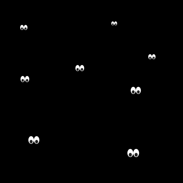
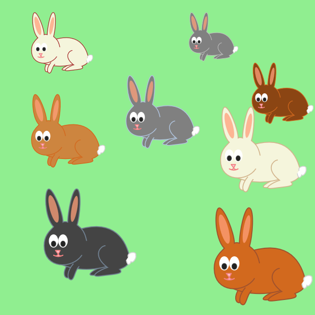
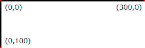
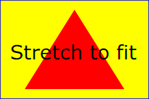
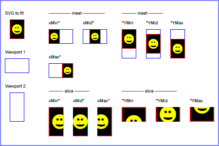
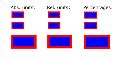


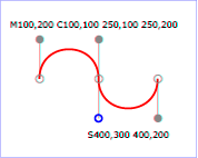
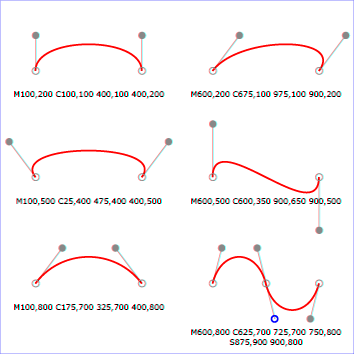
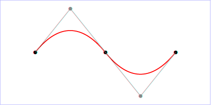
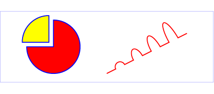
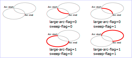

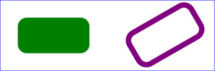
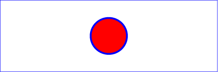
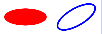
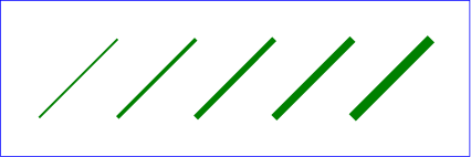
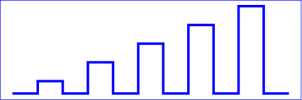
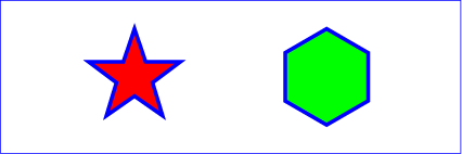


![Examples of using the 'vertical-align' property. Left shows '[[z]]' where the inner brackets are smaller. Right shows 'x2' where the '2' is a superscript.](images/text/vertical_align.svg)


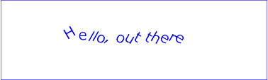
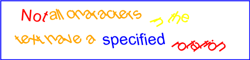
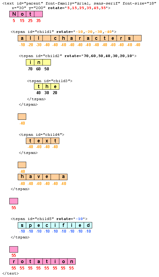


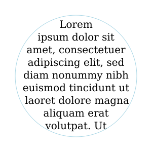

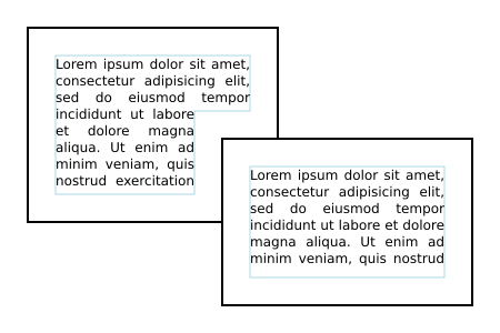


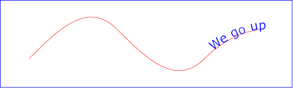

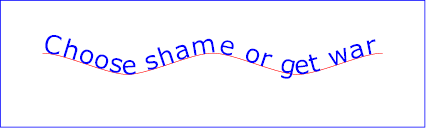
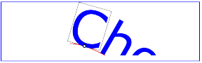
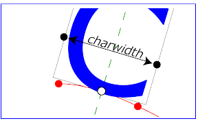


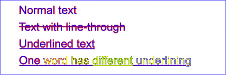


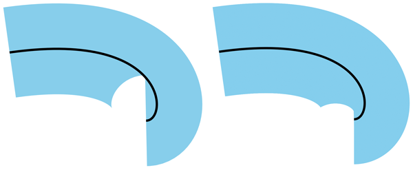


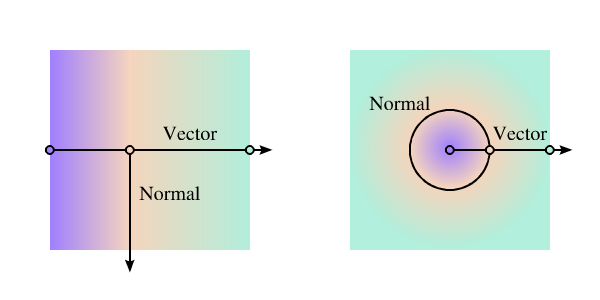
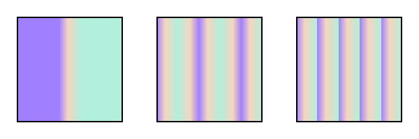
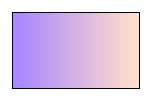
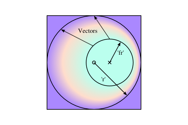
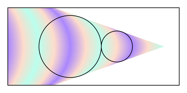
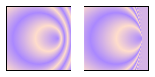
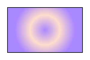
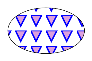
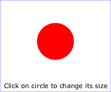
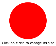
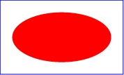
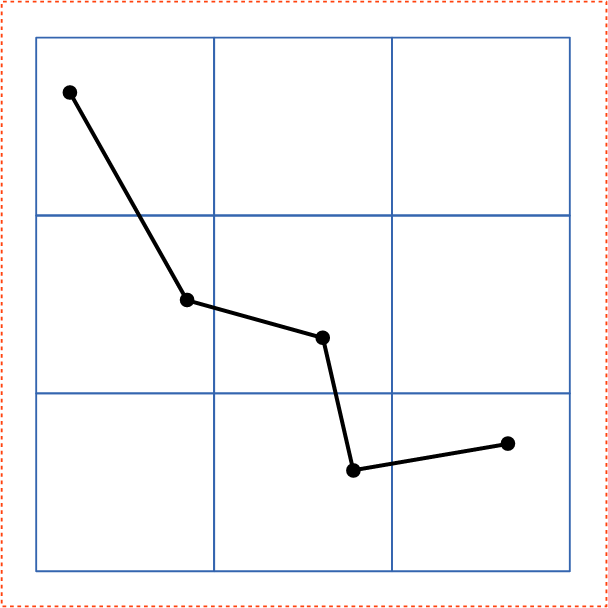
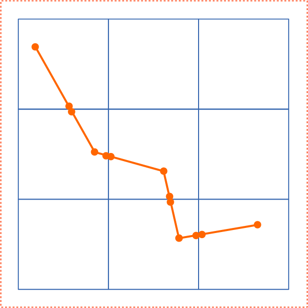
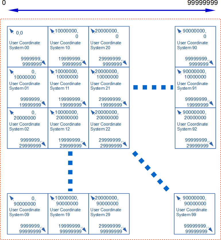
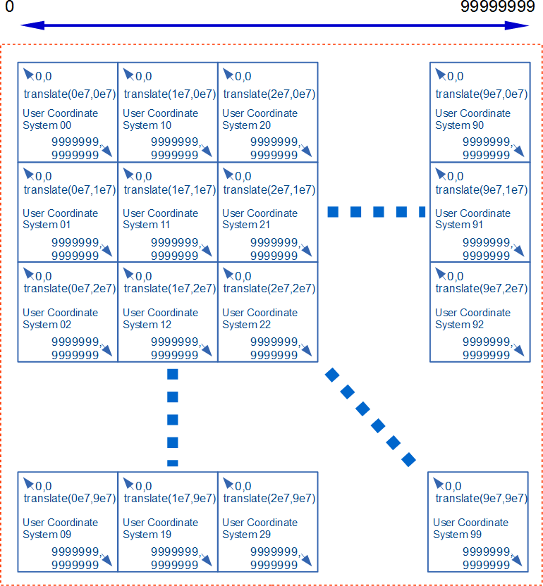