13.1. Introduction
13.1.1. Definitions
- fill
- The operation of painting the interior of a
shape or the interior of the
character glyphs in a text string.
- stroke
- The operation of painting the outline
of a shape or the outline of
character glyphs in a text string.
Graphical elements that define a shape – ‘path’ elements, basic shapes,
and text content elements – are rendered by being filled,
which is painting the interior of the object, and stroked, which is
painting along the outline of the object. Filling and stroking are both
painting operations. SVG 2 supports a number of
different paints that the fill and stroke of a graphical element can be painted with:
- a single color,
- a gradient (linear or radial)
- a pattern (vector or raster, possibly tiled),
- other images as specified using CSS Image Value syntax [css-images-3].
The paint to use for filling and stroking an element is specified using the
fill and stroke properties. The following section describes
the different values that can be used for these properties.
Other properties, such as fill-opacity and stroke-width,
also have an effect on the way fill and stroke paint is applied to the
canvas. The Fill properties and Stroke properties
sections below describe these properties.
Some graphics elements – ‘path’ elements and basic shapes – can also have marker symbols
drawn at their vertices or at other positions along the path that
they describe. The Markers section below describes
how markers can be defined and used.
SVG 2 adds markers on shapes. Resolved at
Tokyo F2F.
13.2. Specifying paint
The fill and stroke properties, defined below, are used to
specify the paint used to render the interior of and the
stroke around shapes and text. A paint specification describes a way of putting
color values on to the canvas and is composed of one or more paint layers.
Four types of paints within these paint layers are supported:
solid colors,
gradients, and
patterns.
A <paint> value is defined as follows:
<paint>
= none
| <color>
| <url> [none | <color>]?
| context-fill | context-stroke
With the possible values:
- none
- No paint is applied in this layer.
- <url> [none | <color>]?
- A URL reference to a paint server element,
which is an element that defines a paint server:
‘linearGradient’, ‘pattern’ and ‘radialGradient’, optionally followed by a fall-back
value that is used if the paint server reference cannot be resolved.
- <color>
- A solid color paint.
- context-fill
- Use the paint value of fill from a context element.
- context-stroke
- Use the paint value of stroke from a context element.
A <paint> allows a paint server reference, to be optionally followed
by a <color> or the keyword none.
When this optional value is given, the <color> value or the value
none is a fallback value to use if the paint
server reference in the layer is invalid (due to pointing to an element that
does not exist or which is not a valid paint server).
Note that this is slightly different from CSS background syntax, where
a background image and color specified in the final layer of a background
value will result in both the image and color being rendered.
If a paint server reference in a <paint> is invalid, and no
fall-back value is given, no paint is rendered for that layer.
This is changed from SVG 1.1 behavior where the document
is in error if a paint server reference is invalid and there is no fallback
color specified.
<rect width="100" height="100" fill="url(#MyHatch) powderblue">
For any <color> value, all color syntaxes
defined in CSS Color Module Level 3
must be supported, including rgb(),
rgba(),
hsl(),
hsla(),
the extended color keywords and
the currentColor value.
The context-fill and context-stroke
values are a reference to the paint layers generated for the fill or stroke
property, respectively, of the context element
of the element being painted. The context element of an element is defined as follows:
- If the element is within a ‘marker’, and
is being rendered as part of that marker due to being referenced
via a marker property, then the context element
is the element referencing that ‘marker’.
- If the element is within a sub-tree that is instantiated
with a ‘use’ element, then the context element is
that ‘use’ element.
- Otherwise, there is no context element.
If there is no context element and these keywords are used, then no paint is
applied.
When the context paint layers include paint server references, then the
coordinate space and the bounding box used
to scale the paint server elements and content are
those of the context element.
In other words, any gradients and patterns referenced with these keywords
should be continuous from the main shape to the markers,
or from one element within a use-element shadow tree to another.
If the referenced value of fill or stroke is a
context-fill and context-stroke
value, then those contextual referencing is recursive.
<svg xmlns="http://www.w3.org/2000/svg" viewBox="0 0 100 100">
  <style>
    path {
      fill: none;
      stroke-width: 4px;
      marker: url(#diamond);
    }
  </style>
  <path d="M 10,50 v -20 h 40 v -20" stroke="red"/>
  <path d="M 30,70 v -20 h 40 v -20" stroke="green"/>
  <path d="M 50,90 v -20 h 40 v -20" stroke="blue"/>
  <marker id="diamond" markerWidth="12" markerHeight="12" refX="6" refY="6"
          markerUnits="userSpaceOnUse">
    <circle cx="6" cy="6" r="3"
            fill="white" stroke="context-stroke" stroke-width="2"/>
  </marker>
</svg>
13.3. The effect of the ‘color’ property
See the CSS Color Module Level 3 specification for the
definition of color.
[css-color-3]
The color property is used to provide a potential indirect value,
currentColor, for the fill,
stroke, stop-color, flood-color and
lighting-color properties. The property has no other effect
on SVG elements.
The following example shows how the inherited value of the
color property from an HTML document can be used to
set the color of SVG text in an inline SVG fragment.
<!DOCTYPE html>
<style>
body { color: #468; font: 16px sans-serif }
svg { border: 1px solid #888; background-color: #eee }
</style>
<p>Please see the diagram below:</p>
<svg width="200" height="100">
  <g fill="currentColor">
    <text x="70" y="55" text-anchor="end">START</text>
    <text x="130" y="55">STOP</text>
    <path d="M 85,45 h 25 v -5 l 10,10 -10,10 v -5 h -25 z"/>
  </g>
</svg>
13.4. Fill properties
13.4.1. Specifying fill paint: the ‘fill’ property
The fill property paints the interior of the given graphical
element. The area to be painted consists of any areas inside the outline
of the shape. To determine the inside of the shape, all subpaths are
considered, and the interior is determined according to the rules
associated with the current value of the fill-rule property.
The zero-width geometric outline of a shape is included in the area to
be painted.
The fill operation fills open subpaths by performing the fill
operation as if an additional "closepath" command were added to the
path to connect the last point of the subpath with the first point of
the subpath. Thus, fill operations apply to both open subpaths within
‘path’ elements (i.e., subpaths without a closepath command) and
‘polyline’ elements.
13.4.2. Winding rule: the ‘fill-rule’
property
The fill-rule property indicates the algorithm (or
winding rule) which is to
be used to determine what parts of the canvas are included inside the
shape. For a simple, non-intersecting path, it is intuitively clear
what region lies "inside"; however, for a more complex path, such as a
path that intersects itself or where one subpath encloses another, the
interpretation of "inside" is not so obvious.
The fill-rule property provides two options for how the
inside of a shape is determined:
- nonzero
-
This rule determines the "insideness" of a point on the
canvas by drawing a ray from that point to infinity in any
direction and then examining the places where a segment of
the shape crosses the ray. Starting with a count of zero,
add one each time a path segment crosses the ray from left
to right and subtract one each time a path segment crosses
the ray from right to left. After counting the crossings,
if the result is zero then the point is outside
the path. Otherwise, it is inside. The following
drawing illustrates the nonzero
rule:
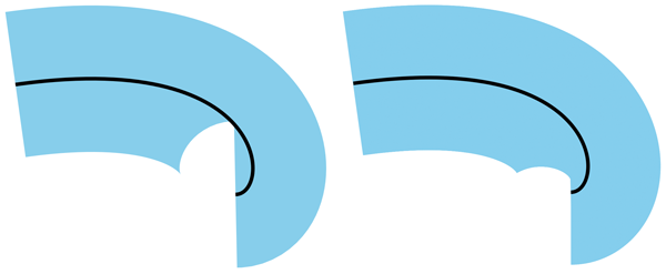
- evenodd
-
This rule determines the "insideness" of a point on the
canvas by drawing a ray from that point to infinity in any
direction and counting the number of path segments from the
given shape that the ray crosses. If this number is odd,
the point is inside; if even, the point is outside. The
following drawing illustrates the evenodd
rule:
The above descriptions do not specify what to do if a path
segment coincides with or is tangent to the ray. Since any ray will do,
one may simply choose a different ray that does not have such problem
intersections.
13.4.3. Fill paint opacity: the ‘fill-opacity’
property
| Name: |
fill-opacity |
| Value: |
<‘opacity’> |
| Initial: |
1 |
| Applies to: |
shapes and text content elements |
| Inherited: |
yes |
| Percentages: |
N/A |
| Media: |
visual |
| Computed value: |
the specified value converted to a number, clamped to the range [0,1] |
| Animation type: |
by computed value |
fill-opacity specifies the opacity of the painting operation used
to paint the fill the current object. (See
Painting shapes and text).
- <number>
-
The opacity of the fill. Any values outside the
range 0 (fully transparent) to 1 (fully opaque) must be
clamped to this range.
- <percentage>
-
The opacity of the fill expressed as a percentage
of the range 0 to 1.
See also the opacity property, which
specifies group opacity.
13.5. Stroke properties
In this section, we define a number of properties that allow the
author to control different aspects of a stroke, including its paint,
thickness, use of dashing, and joining and capping of
path segments.
In all cases, all stroking properties which are affected by
directionality, such as those having to do with dash patterns, must be
rendered such that the stroke operation starts at the same point at
which the graphics element starts. In particular, for ‘path’
elements, the start of the path is the first point of the initial
"moveto" command.
For stroking properties such as dash patterns whose computations
are dependent on progress along the outline of the graphics element,
distance calculations are required to utilize the SVG user agent's
standard Distance along a path
algorithms.
When stroking is performed using a complex paint server, such as a
gradient or a pattern, the stroke operation must be identical to the
result that would have occurred if the geometric shape defined by the
geometry of the current graphics element and its associated stroking
properties were converted to an equivalent ‘path’ element and
then filled using the given paint server.
13.5.1. Specifying stroke paint: the ‘stroke’
property
The stroke property paints along the outline of the given
graphical element.
Note that when stroking a ‘path’ element,
any subpath consisting of a moveto
but no following line drawing command will not be stroked.
Any other type of zero-length subpath, such as
'M 10,10 L 10,10'
or 'M 30,30 Z'
will also not be stroked if the stroke-linecap property has a value of
butt. See the definition of
the stroke shape below for the details of computing
the stroke of a path.
13.5.2. Stroke paint opacity: the ‘stroke-opacity’
property
| Name: |
stroke-opacity |
| Value: |
<‘opacity’> |
| Initial: |
1 |
| Applies to: |
shapes and text content elements |
| Inherited: |
yes |
| Percentages: |
N/A |
| Media: |
visual |
| Computed value: |
the specified value converted to a number, clamped to the range [0,1] |
| Animation type: |
by computed value |
The stroke-opacity property specifies the opacity of the
painting operation used to stroke the current object. (See
Painting shapes and text.)
As with fill-opacity.
- <number>
-
The opacity of the stroke. Any values outside the
range 0 (fully transparent) to 1 (fully opaque) must be
clamped to this range.
- <percentage>
-
The opacity of the stroke expressed as a percentage
of the range 0 to 1.
See also the opacity property, which specifies
group opacity.
13.5.3. Stroke width: the ‘stroke-width’
property
This property specifies the width of the stroke on the current object.
A zero value causes no stroke to be painted. A negative value
is invalid. A <number> value represents a value in user units.
13.5.4. Drawing caps at the ends of strokes: the ‘stroke-linecap’
property
| Name: |
stroke-linecap |
| Value: |
butt | round | square |
| Initial: |
butt |
| Applies to: |
shapes and text content elements |
| Inherited: |
yes |
| Percentages: |
N/A |
| Media: |
visual |
| Computed value: |
as specified |
| Animation type: |
discrete |
stroke-linecap specifies the shape to be used at the end of
open subpaths when they are stroked,
and the shape to be drawn for zero length
subpaths whether they are open or closed. The possible values are:
- butt
- This value indicates that the stroke for each subpath does not
extend beyond its two endpoints. A zero length subpath will therefore
not have any stroke.
- round
-
This value indicates that at each end of each subpath, the shape
representing the stroke will be extended by a half circle with a diameter equal
to the stroke width. If a subpath, whether open or closed, has zero length,
then the resulting effect is that the stroke for that subpath consists solely
of a full circle centered at the subpath's point.
- square
-
This value indicates that at the end of each subpath, the shape
representing the stroke will be extended by a rectangle with the
same width as the stroke width and whose length is half of the stroke width.
If a subpath, whether open or closed, has zero length, then the resulting
effect is that the stroke for that subpath consists solely of a square with
side length equal to the stroke width, centered at the subpath's point, and
oriented such that two of its sides are parallel to the effective tangent
at that subpath's point. See
‘path’
element implementation notes for details on how to determine the tangent
at a zero-length subpath.
See the definition of the cap shape below for a more precise
description of the shape a line cap will have.
13.5.5. Controlling line joins: the ‘stroke-linejoin’
and ‘stroke-miterlimit’ properties
The values miter-clip and arcs
of the stroke-linejoin property are at risk. There are no known browser implementations.
See issue GitHub issue #592.
| Name: |
stroke-linejoin |
| Value: |
miter | miter-clip | round | bevel | arcs |
| Initial: |
miter |
| Applies to: |
shapes and text content elements |
| Inherited: |
yes |
| Percentages: |
N/A |
| Media: |
visual |
| Computed value: |
as specified |
| Animation Type: |
discrete |
stroke-linejoin specifies the shape to be used at the
corners of paths or basic shapes when they are stroked. For further details see
the path implementation notes.
- miter
- This value indicates that a sharp corner is to be used to join path segments.
The corner is formed by extending the outer edges of the stroke at the tangents
of the path segments until they intersect. If the stroke-miterlimit
is exceeded, the line join falls back to bevel
(see below).
- miter-clip
- This value is the same as miter but if
the stroke-miterlimit is exceeded, the miter is clipped at a
distance equal to half the stroke-miterlimit value multiplied
by the stroke width from the intersection of the path segments
(see below).
- round
- This value indicates that a round corner is to be used to join path segments.
The corner is a circular sector centered on the join point.
- bevel
- This value indicates that a bevelled corner is to be used to join path segments.
The bevel shape is a triangle that fills the area between the two stroked segments.
- arcs
- This value indicates that an arcs corner is to be used to join
path segments. The arcs shape is formed by extending the outer
edges of the stroke at the join point with arcs that have the same
curvature as the outer edges at the join point.
The miter-clip and
arcs values are new in SVG 2.
The miter-clip value offers a more
consistent presentation for a path with multiple joins as well as
better behavior when a path is animated.
The arcs value provides a better
looking join when the path segments at the join are curved.
Adding 'arcs' line join was resolved at the
Rigi
Kaltbad group meeting.
Adding 'miter-clip' line join was resolved at the
Sydney
(2015) group meeting.
When two line segments meet at a sharp angle and a value of
miter,
miter-clip, or
arcs has been specified for
stroke-linejoin, it is possible for the join to extend
far beyond the thickness of the line stroking the path. The
stroke-miterlimit imposes a limit on the extent of the
line join.
- <number>
-
The limit on the extent of a
miter,
miter-clip, or
arcs line join as a multiple of
the stroke-width value.
A negative value for stroke-miterlimit is invalid and must be ignored.
Previous versions of the SVG specification
also stated that values between 0 and 1 were in error,
but this was not well implemented by user agent's CSS parsers.
In practice, any miter join will exceed a miter limit between 0 and 1.
For the miter or the
miter-clip values, given
the angle θ between the segments in user coordinate system,
the miter length is calculated by:
miter length = stroke-width / sin(theta / 2)
Historically, the miter length is defined as the distance from the
inside stroke edge of the intersecting path segments to the tip of
the miter. In practice, this is followed only for straight path
segments. The above definition of miter length based on angles
depends only on the tangents to the path segments at the join and
thus gives consistent results independent of the curvature of the
path segments. To be consistent with this definition, the clipping
point of the
miter-clip and
arcs line joins is at a distance
or arc length equal to half the stroke-miterlimit times
the stroke width from the point the two path segments join.
If the miter length divided by the stroke width exceeds the
stroke-miterlimit then for the value:
- miter
-
the join is converted to a bevel;
- miter-clip
-
the miter is clipped by a line perpendicular to the line bisecting
the angle between the two path segments at a distance of half the value
of miter length from the intersection of the two path segments.
For the arcs value, the
miter length is calculated along a circular arc that is
tangent to the line bisecting the angle between the two segments at
the point the two segments intersect and passes through the end
point of the join. The line join is clipped, if necessary, by a line
perpendicular to this arc at an arc length from the intersection
point equal to half the value of the stroke-miterlimit value
multiplied by the stroke width.
The effect of 'stroke-miterlimit' on an 'arcs' line join was resolved
at Sydney
(2015) group meeting.
See the definition of the line join shape below for a more
precise description of the shape a line join will have.
13.5.6. Dashing strokes: the ‘stroke-dasharray’ and
‘stroke-dashoffset’ properties
| Name: |
stroke-dasharray |
| Value: |
none | <dasharray> |
| Initial: |
none |
| Applies to: |
shapes and text content elements |
| Inherited: |
yes |
| Percentages: |
refer to the normalized diagonal of the current SVG viewport (see Units) |
| Media: |
visual |
| Computed value: |
as comma separated list of absolute lengths or percentages, numbers converted to absolute lengths first, or keyword specified |
| Animation type: |
See prose |
where:
<dasharray> =
[ [ <length-percentage> | <number> ]+ ]#
The stroke-dasharray property controls
the pattern of dashes and gaps used to form the shape of
a path's stroke.
- none
- Indicates that no dashing is used.
- <dasharray>
-
Specifies a dashing pattern to use. A <dasharray> is
a list of comma and/or white space separated <number> or
<length-percentage> values.
A <number> value represents a value in user units.
Each value specifies a length along the path for which the stroke
is to be painted (a dash) and not painted (a gap).
The first value and every second value in the list after it specifies
the length of a dash, and every other value specifies the length of a gap
between the dashes. If the list has an odd number of values, then it is
repeated to yield an even number of values. (Thus, the rendering behavior
of stroke-dasharray: 5,3,2
is equivalent to stroke-dasharray: 5,3,2,5,3,2.)
The resulting even-length dashing pattern is repeated along each subpath.
The dashing pattern is reset and begins again at the start of each subpath.
If any value in the list is negative, the <dasharray> value is
invalid. If all of the values in the list are zero,
then the stroke is rendered as a solid line without any dashing.
The ‘pathLength’ attribute on a ‘path’ element affects
stroke-dasharray: each dash and gap length is interpreted relative
to the author's path length as specified by ‘pathLength’.
stroke-dasharray values are not additive. For interpolation,
stroke-dasharray values are combined as follows:
- If either start or end compute to none or are invalid
- start or end are combined using the discrete animation type.
- Otherwise
- repeat both dash patterns of start and end value list until the length of elements in
both value lists match. Each item is then combined by computed value.
The two
stroke-dasharray value lists in the following example have different number
of elements:
path {
  stroke-dasharray: 20 40 10;
}

path:hover {
  transition-property: stroke-dasharray;
  transition-duration: 0.5s;
  stroke-dasharray: 40 20;
}
To interpolate the two value lists the dash pattern gets repeated on both lists first:
stroke-dasharray: 20 40 10 20 40 10;
stroke-dasharray: 40 20 40 20 40 20;
After that, each item is then combined by computed value.
The stroke-dashoffset property specifies the distance into the repeated
dash pattern to start the stroke dashing at the beginning of the path. If the
value is negative, then the effect is the same as dash offset d:
d = s - (abs(stroke-dashoffset) mod s)
where s is the sum of the dash array values.
Like stroke-dasharray, stroke-dashoffset is interpreted
relative to the author's path length as specified by the ‘pathLength’
attribute on a ‘path’ element.
The example below shows how a ‘pathLength’ that is greatly
different from the actual path length can be used to control stroke
dashing more easily.
<svg xmlns="http://www.w3.org/2000/svg" xmlns:xlink="http://www.w3.org/1999/xlink"
     width="300" height="150">
  <defs>
    <path id="p" d="M -50,0 A 50,50 0 0 0 50,0 A 50,50 0 0 0 -50,0 z"
          pathLength="80"/>
    <g id="chip" stroke-width="10">
      <circle cy="5" r="55" fill="#000" fill-opacity="0.15" stroke="none"/>
      <use xlink:href="#p"/>
      <use xlink:href="#p" fill="none" stroke="#eee" stroke-width="10"
           stroke-dasharray="10 10" stroke-dashoffset="5"/>
      <g fill="none" stroke-width="5" stroke-dasharray="0 20" stroke-linecap="round">
        <use xlink:href="#p" stroke="#eee" stroke-dashoffset="10"/>
        <use xlink:href="#p" stroke-dashoffset="0"/>
      </g>
      <circle r="40" fill="#000" fill-opacity="0.15"
              stroke-width="2" stroke="white"/>
    </g>
  </defs>
  <rect width="100%" height="100%" fill="#063"/>
  <use xlink:href="#chip" x="140" y="75" fill="#00c" stroke="#00c"/>
  <use xlink:href="#chip" x="160" y="85" fill="#000" stroke="#000"/>
  <use xlink:href="#chip" x="170" y="65" fill="#c00" stroke="#c00"/>
</svg>
See the definition of dash positions below for a more precise
description of positions along a path that dashes will be placed.
13.5.7. Computing the shape of the stroke
The stroke shape of an element is the
shape that is filled by the stroke property. Since ‘text’
elements can be rendered in multiple chunks, each chunk has its own
stroke shape. The following algorithm describes the ideal stroke shape
of a ‘path’, basic shape or individual ‘text’ chunk is,
taking into account the stroking properties above. The ideal stroke shape
described defines a best case implementation, but implementations are given some
leeway to deviate from this description for performance reasons.
Authors should be aware that the shape of a stroke may in some cases, such as
at extremely tight curves, differ across platforms.
The above example shows the possible rendered results for the following
two SVG paths:
<svg viewBox="0 0 10 10" xmlns="http://www.w3.org/2000/svg">
<path d="M 1,3 C 8,2 8,6 7,6" stroke-width="4" fill="none" stroke="skyblue"/>
<path d="M 1,3 C 8,2 8,6 7,6" stroke-width="0.075" fill="none" stroke="black"/>
</svg>
The ideal stroke shape is determined as follows:
- Let shape be an empty shape.
- If stroke-width > 0, then:
- Let scale be a scale factor for the dash pattern. If we are
computing the stroke shape of a ‘text’ chunk,
or if the ‘pathLength’ attribute is not present on the element,
then scale is 1. Otherwise, it is determined as follows:
- Let length be the user agent's computed length of the
‘path’ or equivalent path for a basic shape.
- Let authorlength be the value of the ‘pathLength’
attribute on the shape.
- scale is authorlength / length.
- Let path be the equivalent path of the element (or the individual
chunk of a ‘text’ element).
- For each subpath of path:
- Let positions be the dash positions for the subpath.
- For each pair <start, end> in positions:
- Scale start and end by scale.
- Let dash be the shape that includes, for all distances
between start and end along the subpath, all
points that lie on the line perpendicular to the subpath at that
distance and which are within distance stroke-width of
the point on the subpath at that position.
- Set dash to be the union of dash and the
starting cap shape for the subpath at position start.
- Set dash to be the union of dash and the
ending cap shape for the subpath at position end.
-
Let index and last be the indexes of the
path segments in the subpath at distance start and
end along the subpath.
It does not matter whether any zero length segments are
included when choosing index and last.
- While index < last:
- Set dash to be the union of dash and the
line join shape for the subpath at segment index index.
- Set index to index + 1.
- Set shape to be the union of shape and
stroke.
- Return shape.
The dash positions for a given subpath of
the equivalent path of a ‘path’ or basic shape is a
sequence of pairs of values, which represent the starting and ending distance
along the subpath for each of the dashes that form the subpath's stroke. It is
determined as follows:
- Let pathlength be the length of the subpath.
- Let dashes be the list of values of stroke-dasharray
on the element, converted to user units, repeated if necessary so that it has
an even number of elements; if the property has the value
none, then the list has a single value 0.
- Let count be the number of values in dashes.
- Let sum be the sum of the values in dashes.
- If sum = 0, then return a sequence with the single pair
<0, pathlength>.
- Let positions be an empty sequence.
- Let offset be the value of the stroke-dashoffset
property on the element.
- If offset is negative, then set offset to
sum − abs(offset).
- Set offset to offset mod sum.
- Let index be the smallest integer such that
sum(dashesi, 0 ≤ i ≤ index) ≥ offset.
- Let dashlength be
min(sum(dashesi, 0 ≤ i ≤ index) − offset, pathlength).
- If index mod 2 = 0, then append to positions the
pair <0, dashlength>.
- Let position be dashlength.
- While position < pathlength:
- Set index to (index + 1) mod count.
- Let dashlength be
min(dashesindex, pathlength − position).
- If index mod 2 = 0, then append to positions the
pair <position, position + dashlength>.
- Set position to position + dashlength.
- Return positions.
The starting and ending cap shapes at a given
position along a subpath are determined as follows:
- If stroke-linecap is butt, then return an empty shape.
- Otherwise, if stroke-linecap is round, then:
- If this is a starting cap, then return a semicircle of diameter stroke-width positioned such that:
- The subpath that the semicircle is relative to is the subpath starting
at distance position.
- Its straight edge is parallel to the line perpendicular to the subpath at distance position along it.
- The midpoint of its straight edge is at the point that is along the subpath at distance position.
- The direction from the midpoint of its arc to the midpoint of its straight edge is the same as the direction of
the subpath at distance position.
- Otherwise, this is an ending cap. Return a semicircle of diameter stroke-width positioned such that:
- The subpath that the semicircle is relative to is the subpath ending
at distance position.
- Its straight edge is parallel to the line perpendicular to the subpath at distance position along it.
- The midpoint of its straight edge is at the point that is along the subpath at distance position.
- The direction from the midpoint of its straight edge to the midpoint of its arc is the same as the
direction of the subpath.
- Otherwise, stroke-linecap is square:
- If this is a starting cap, then return a rectangle with side lengths stroke-width and stroke-width / 2 positioned such that:
- Its longer edges, A and B, are parallel to the line perpendicular to the subpath at distance position along it.
- The midpoint of A is at start.
- The direction from the midpoint of B to the midpoint of A is the same as the direction of the subpath at distance position along it.
- Otherwise, this is an ending cap. Return a rectangle with side lengths stroke-width and stroke-width / 2 positioned such that:
- Its longer edges, A and B, are parallel to the line perpendicular to the subpath at distance position along it.
- The midpoint of A is at end.
- The direction from the midpoint of A to the midpoint of B is the same as the direction of the subpath at distance position along it.
The line join shape for a given segment of
a subpath is determined as follows:
- Let P be the point at the end of the segment.
- If the unit tangent vector at the end of the segment and the unit tangent vector
at the start of the following segment are equal, then return an empty shape.
This means for example that 'M 100,100 h 100 h 100'
would not produce a line join shape between the two straight line segment, but
'M 100,100 h 100 h -100' would.
- Let A be the line parallel to the tangent at the end of the segment.
- Let B be the line parallel to the tangent at the start of the following segment.
- Let Aleft and Aright be lines
parallel to A at a distance of stroke-width / 2 to the
left and to the right of A relative to the subpath direction, respectively.
- Let Bleft and Bright be lines
parallel to B at a distance of stroke-width / 2 to the
left and to the right of B, relative to the subpath direction, respectively.
-
Let P1, P2 and
P3 be points determined as follows:
- If the smaller angle between A and B is on the
right of these lines, considering the direction of the subpath, then
P1 and P2 are the points on
Aleft and Bleft closest to
P, and P3 is the intersection of
Aleft and Bleft.
- Otherwise, P1 and P2 are
the points on Aright and Bright
closest to P, and P3 is the intersection
of Aright and Bright.
- Let bevel be the triangle formed from the three points
P, P1 and P2.
- If stroke-linejoin is round, then
return the union of bevel and a circular sector of diameter
stroke-width, centered on P, and which has
P1 and P2 as the two endpoints of
the arc.
- If stroke-linejoin is arcs,
then find the circles that are tangent to the stroke edges at
P1 and P2 with the
same curvature as the edges at those points (see below). If both
curvatures are zero fall through to miter-clip.
If either curvature is greater than 2/(stroke width), fallback to
round.
Extend the stroke edges using these circles (or a line, in the case
of zero curvature).
If the two circles (or circle and line) do not intersect, adjust
the radii of the two circles by an equal amount (or just the circle
in case of a circle and line) until they do intersect (see below).
The line join
region is defined by the lines that connect P
with P1 and P2 and the
arcs defined by the circles (or arc and line) between the closest
intersection point to P, and P1
and P2.
Next calculate the miter limit as defined in
the stroke-miterlimit section. Clip any part of the line
join region that extends past the miter limit. Return the
resulting region.
Note that the curvatures are calculated in user-space before any
transforms are applied.
-
If stroke-linejoin is miter or
miter-clip then the line join
region is the union of bevel and the triangle formed
from the three points P1,
P2 and P3.
-
Let θ be the angle between A and B.
If 1 / sin(θ / 2) ≤ stroke-miterlimit, then return
the line join region.
-
If stroke-linejoin is miter-clip,
then clip any part of the line join region that extends past the
miter limit and return this region.
- Return bevel.
13.5.8. Computing the circles for the arcs
'stroke-linejoin'
The arcs stroke-linejoin
requires finding circles that are both tangent to and have the same
curvatures as the outer stroke edges at the ends of path
segments. To find one of these circles, first calculate the
curvature κ of the path segment at its end (see
below). Next, find the radius of a circle corresponding to this
curvature: r = 1/κ. Increase or
decrease the radius by one half of the stroke width to account for
the stroke: rc = r ± ½
stroke-width. The center of the circle will be on a line normal to
the path end a distance of rc away from the
outer stroke edge at the end.
For a line: the curvature is zero. Extend the outer stroke edge by a line.
For an elliptical arc:
$$\kappa(t) = {{r_x r_y}\over{(r_x^2 \sin^2 t + r_y^2 \cos^2 t)^{3/2}}}$$
where:
$$t = \arctan \left( {r_y \over r_x} \tan \theta \right)$$
The parameter θ at the beginning or end of an
arc segment can be found by using the formulas in
the Elliptical arc
implementation notes. (Note, some renderers convert elliptical
arcs to cubic Béziers prior to rendering so the equations here may
not be needed.)
For a quadratic Bézier:
$$\kappa(0) = {2\over3}{(P_1-P_0)\times((P_0-P_1)+(P_2-P_1))\over|P_1-P_0|^3}$$
$$\kappa(0) = {2\over3}{(P_1-P_0)\times((P_0-P_1)+(P_2-P_1))\over|P_1-P_0|^3}$$
Where κ(0) and κ(1) are the
signed curvatures at the start and end of the path segment
respectively, and the P's are the three points that
define the quadratic Bézier.
For a cubic Bézier:
$$\kappa(0) = {2\over3}{(P_1-P_0)\times((P_0-P_1)+(P_2-P_1))\over|P_1-P_0|^3}$$
$$\kappa(1) = {2\over3}{(P_3-P_2)\times((P_1-P_2)+(P_3-P_2))\over|P_3-P_2|^3}$$
Where κ(0) and κ(1) are the
signed curvatures at the start and end of the path segment
respectively, and the P's are the four points that define
the cubic Bézier. Note, if
P0 and P1, or
P2 and P3 are degenerate, the
curvature will be infinite and a line should be used in constructing the join.
13.5.9. Adjusting the circles for the arcs
'stroke-linejoin' when the initial circles do not intersect
The fallback behavior was resolved at
the Sydney
2016 F2F. It gives a smooth transition between the fallback
and non-fallback states.
When the initial circles calculated for the
arcs stroke-linejoin do
not intersect, they need to be adjusted by changing both radii by
the same magnitude (moving the circle centers to keep the circles
tangent to the offset paths) until the circles just touch. There
are two cases to consider. The first is when one circle encloses
the other circle. In this case the larger circle is reduced in
size while the smaller circle is increased in size:
The second case is when there is no overlap between the circles.
In this case the radii of both circles are increased by the same
amount:
If in this latter case, the tangents of the offset paths at the
line join are parallel, the circles cannot be adjusted so that
they touch. The line join should then be constructed as a
rectangle whose width is the stroke width and whose length is the
stroke width times one half of the value of the
stroke-miterlimit:
There are a couple of ways to implement the fallback algorithm. The first
way is by recursive trial and error on the magnitude of the radius change.
The second is by an exact calculation utilizing the touching circle
condition and the constraints that the centers of the circles must
remain on lines normal to the path segments at the join. This leads to
a quadratic equation where one solution is the required radius change.
13.7. Markers
A marker is a graphical object that is painted at particular positions along
any shape element.
The marker-start and marker-end properties
can be used to place markers at the first and last vertex of a
shape, and the marker-mid property can be used
to place markers at all other vertices (aside from the first and last).
The marker-start and marker-end can be used for example to
add arrowheads to paths. Markers placed using these properties are known as
vertex markers.
In SVG 2, vertex markers are the only kind of markers
available. Other specifications will add new types of markers.
The graphics for a marker are defined by a ‘marker’ element.
The marker-start, marker-end and marker-mid properties,
together known as the marker properties, reference
‘marker’ elements.
Markers can be animated, and as with ‘use’ elements, the animated
effects will show on all current uses of the markers within the document.
Markers on a given element are painted in the following order, from
bottom to top:
13.7.1. The ‘marker’ element
‘marker’
- Categories:
- Container element, never-rendered element
- Content model:
- Any number of the following elements, in any order:
- animation elements — ‘animate’, ‘animateMotion’, ‘animateTransform’, ‘set’
- descriptive elements — ‘desc’, ‘title’, ‘metadata’
- paint server elements — ‘linearGradient’, ‘radialGradient’, ‘pattern’
- shape elements — ‘circle’, ‘ellipse’, ‘line’, ‘path’, ‘polygon’, ‘polyline’, ‘rect’
- structural elements — ‘defs’, ‘g’, ‘svg’, ‘symbol’, ‘use’
a, clipPath, filter, foreignObject, image, marker, mask, script, style, switch, text, view - Attributes:
- core attributes — ‘id’, ‘tabindex’, ‘autofocus’, ‘lang’, ‘xml:space’, ‘class’, ‘style’
- global event attributes — ‘oncancel’, ‘oncanplay’, ‘oncanplaythrough’, ‘onchange’, ‘onclick’, ‘onclose’, ‘oncopy’, ‘oncuechange’, ‘oncut’, ‘ondblclick’, ‘ondrag’, ‘ondragend’, ‘ondragenter’, ‘ondragexit’, ‘ondragleave’, ‘ondragover’, ‘ondragstart’, ‘ondrop’, ‘ondurationchange’, ‘onemptied’, ‘onended’, ‘onerror’, ‘onfocus’, ‘oninput’, ‘oninvalid’, ‘onkeydown’, ‘onkeypress’, ‘onkeyup’, ‘onload’, ‘onloadeddata’, ‘onloadedmetadata’, ‘onloadstart’, ‘onmousedown’, ‘onmouseenter’, ‘onmouseleave’, ‘onmousemove’, ‘onmouseout’, ‘onmouseover’, ‘onmouseup’, ‘onpaste’, ‘onpause’, ‘onplay’, ‘onplaying’, ‘onprogress’, ‘onratechange’, ‘onreset’, ‘onresize’, ‘onscroll’, ‘onseeked’, ‘onseeking’, ‘onselect’, ‘onshow’, ‘onstalled’, ‘onsubmit’, ‘onsuspend’, ‘ontimeupdate’, ‘ontoggle’, ‘onvolumechange’, ‘onwaiting’, ‘onwheel’
- presentation attributes —
- ‘viewBox’
- ‘preserveAspectRatio’
- ‘refX’
- ‘refY’
- ‘markerUnits’
- ‘markerWidth’
- ‘markerHeight’
- ‘orient’
- DOM Interfaces:
The ‘marker’ element defines the graphics that are to
be used for drawing markers on a shape.
Attribute definitions:
-
| Name |
Value |
Initial value |
Animatable |
| markerUnits |
strokeWidth | userSpaceOnUse |
strokeWidth |
yes |
-
The ‘markerUnits’ attribute defines the coordinate system for
attributes ‘markerWidth’, ‘markerHeight’ and the
contents of the ‘marker’. Values have the
following meanings:
- strokeWidth
- ‘markerWidth’, ‘markerHeight’ and the contents
of the ‘marker’ have values in a coordinate system
which has a single unit equal to the size in user units of the
painted stroke width of the element referencing the marker.
- userSpaceOnUse
- ‘markerWidth’, ‘markerHeight’ and the contents
of the ‘marker’ have values in the current
user coordinate system in place for the element
referencing the marker.
-
When ‘markerUnits’ has the value strokeWidth,
the size of the marker is relative to the stroke-width after it has
had any transforms applied that affect the width of the stroke in the
user coordinate system for the stroke. This means that, for example,
the vector-effect attribute with a value of
non-scaling-stroke will result in the markers
also being non scaling.
-
The ‘markerWidth’ and ‘markerHeight’ attributes
represent the size of the SVG viewport into which the marker is to
be fitted according to the ‘viewBox’ and ‘preserveAspectRatio’
attributes. A value of zero for either
attribute results in nothing being rendered for the marker. A negative value
for either attribute is an error (see
Error processing).
-
-
New in SVG 2: geometric keywords (matches use in ‘symbol’).
We will add top/center/bottom, left/center/right keywords to
refX/refY on marker/symbol. Resolved at
London
F2F. Values inspired by
'background-position'.
The ‘refX’ and ‘refY’ attributes define the reference
point of the marker, which is to be placed exactly at the marker's
position on the shape. Lengths and numbers must be interpreted
as being in the coordinate system of the marker contents, after application of the
‘viewBox’ and ‘preserveAspectRatio’ attributes. Percentage
values must be interpreted as being a percentage of the ‘viewBox’
width for ‘refX’ or a percentage of the ‘viewBox’ height for
‘refY’.
The keyword values must evaluate to the following percentages:
Mapping of refX and refY keywords to percentages.
| keyword | percentage equivalent |
|---|
| left | 0% |
| center | 50% |
| right | 100% |
| top | 0% |
| bottom | 100% |
-
| Name |
Value |
Initial value |
Animatable |
| orient |
auto | auto-start-reverse | <angle> | <number> |
0 |
yes (non-additive) |
-
The ‘orient’ attribute indicates how the marker
is rotated when it is placed at its position on the shape.
Values have the following meanings:
- 'auto'
-
The marker is oriented such that its positive x-axis
is pointing in a direction relative to the path
at the position the marker is placed (See
Rendering Markers).
- 'auto-start-reverse'
-
If placed by marker-start, the marker is oriented
180° different from the orientation that would be used if
'auto' where specified. For
all other markers, 'auto-start-reverse'
means the same as 'auto'.
This allows a single arrowhead marker to be defined
that can be used for both the start and end of a path, i.e. which points
outwards from both ends.
- <angle>
- <number>
-
The marker is oriented such that the specified angle is
that measured between the shape's positive x-axis
and the marker's positive x-axis. A <number> value
specifies an angle in degrees.
For example, if a value of '45'
is given, then the marker's positive x-axis would be pointing down and right
in the shape's coordinate system.
13.7.2. Vertex markers: the ‘marker-start’,
‘marker-mid’ and ‘marker-end’
properties
| Name: |
marker-start,
marker-mid,
marker-end |
| Value: |
none | <marker-ref> |
| Initial: |
none |
| Applies to: |
shapes |
| Inherited: |
yes |
| Percentages: |
N/A |
| Media: |
visual |
| Computed value: |
as specified, but with <url> values (that are part of
a <marker-ref>) made absolute |
| Animation type: |
discrete |
where:
<marker-ref> = <url>
The marker-start and marker-end properties are used
to specify the marker that will be drawn at the first and last vertices
of the given shape, respectively. marker-mid
is used to specify the marker that will be drawn at all other vertices
(i.e., every vertex except the first and last).
Possible values for marker-start, marker-mid and
marker-end are:
- none
- Indicates that no marker symbol will be drawn at the given
vertex or vertices.
- <marker-ref>
- Indicates that the ‘marker’ element referenced
by the <marker-ref> value will be drawn at the given vertex or
vertices.
If the reference is not valid, then no marker will be drawn at the given
vertex or vertices.
For all shapes, the path that must be used when calculating
marker positions is the equivalent path.
For all shape elements, except ‘polyline’ and ‘path’,
the last vertex is the same as the first
vertex. In this case, if the value of marker-start and marker-end
are both not none, then two markers
will be rendered on that final vertex.
For ‘path’ elements, for each closed subpath, the last vertex is
the same as the first vertex. marker-start must only be rendered on
the first vertex of the path data. marker-end must only be
rendered on the final vertex of the path data.
marker-mid must be rendered on every vertex other than the first
vertex of the path data and the last vertex of the path data.
<svg xmlns="http://www.w3.org/2000/svg" viewBox="0 0 100 30">
  <defs>
    <marker id="m1" viewBox="0 0 10 10" refX="5" refY="5"
     markerWidth="8" markerHeight="8">
      <circle cx="5" cy="5" r="5" fill="green"/>
    </marker>
    <marker id="m2" viewBox="0 0 10 10" refX="5" refY="5"
     markerWidth="6.5" markerHeight="6.5">
      <circle cx="5" cy="5" r="5" fill="skyblue" opacity="0.9"/>
    </marker>
    <marker id="m3" viewBox="0 0 10 10" refX="5" refY="5"
     markerWidth="5" markerHeight="5">
      <circle cx="5" cy="5" r="5" fill="maroon" opacity="0.85"/>
    </marker>
  </defs>

  <path d="M10,10 h10 v10 z m20,0 h10 v10 z m20,0 h10 v10 z"
  fill="none" stroke="black"
  marker-start="url(#m1)"
  marker-mid="url(#m2)"
  marker-end="url(#m3)"
  />
</svg>
Note that marker-start and marker-end
refer to the first and last vertex of the entire path, not each subpath.
The following example shows a triangular marker symbol used as a
vertex marker to form an arrowhead at the end of two paths.
<svg xmlns="http://www.w3.org/2000/svg"
     width="275" height="200" viewBox="0 0 275 200">
  <defs>
    <marker id="Triangle" viewBox="0 0 10 10" refX="1" refY="5"
            markerUnits="strokeWidth" markerWidth="4" markerHeight="3"
            orient="auto">
      <path d="M 0 0 L 10 5 L 0 10 z" fill="context-stroke"/>
    </marker>
  </defs>

  <g fill="none" stroke-width="10" marker-end="url(#Triangle)">
    <path stroke="crimson" d="M 100,75 C 125,50 150,50 175,75"/>
    <path stroke="olivedrab" d="M 175,125 C 150,150 125,150 100,125"/>
  </g>
</svg>
13.7.3. Marker shorthand: the ‘marker’
property
| Name: |
marker |
| Value: |
none | <marker-ref> |
| Initial: |
not defined for shorthand properties |
| Applies to: |
shapes |
| Inherited: |
yes |
| Percentages: |
N/A |
| Media: |
visual |
| Computed value: |
see individual properties |
| Animation type: |
discrete |
The marker property sets values for the
marker-start, marker-mid and marker-end
properties. The value of the marker is used
directly for all three of the corresponding longhand properties.
13.7.4. Rendering markers
When orienting a marker automatically, due to specifying ‘orient’
as 'auto', the following rules are used:
For each marker that is drawn, a temporary new user coordinate
system is established so that the marker will be positioned and sized
correctly, as follows:
- The axes of the temporary new user coordinate system are aligned
according to the ‘orient’ attribute on the
‘marker’ element.
- A temporary new coordinate system is established by attribute
‘markerUnits’. If ‘markerUnits’ equals
'strokeWidth', then the temporary new
user coordinate system is the result of scaling the current
user coordinate system by the current value of property
stroke-width. If ‘markerUnits’ equals
'userSpaceOnUse', then no extra scale
transformation is applied.
- An additional set of transformations might occur if the
‘marker’ element includes a ‘viewBox’ attribute, in
which case additional transformations are set up to produce the necessary
result due to attributes ‘viewBox’ and ‘preserveAspectRatio’.
- If the overflow property on the ‘marker’ element
indicates that the marker needs to be clipped to its SVG viewport, then an
implicit clipping path is established at the bounds of the SVG viewport.
Note that the user agent style sheet sets
the overflow property for ‘marker’ elements to
hidden, which causes a rectangular clipping
path to be created at the bounds of marker's SVG viewport by default.
Properties do not inherit from the element referencing the ‘marker’
into the contents of the marker. However, by using the
context-stroke value for the fill or
stroke on elements in its definition, a single marker can be designed
to match the style of the element referencing the marker.
Markers cannot be interacted with. Events such as click or mouseover,
for example, are not dispatched to a ‘marker’ or its children when
the mouse is clicked or moved over a rendered marker.
Markers are not rendered directly
and must be referenced by one of the marker properties
to be rendered.
The display value for the ‘marker’ element
must always be set to none
by the user agent style sheet,
and this declaration must have importance over any other CSS rule or presentation attribute.
‘marker’ elements are available for referencing even when the
display property on the ‘marker’ element or any of its
ancestors is set to none.
The rendering effect of a marker is as if the contents of the
referenced ‘marker’ element were deeply cloned
into a separate non-exposed DOM tree for each instance of the
marker. Because the cloned DOM tree is non-exposed, the SVG DOM
does not show the cloned instance of the marker.
The conceptual deep cloning of the referenced
‘marker’ element into a non-exposed DOM tree also
copies any property values resulting from
the CSS cascade
([CSS2], chapter 6) and
property inheritance on the referenced element and its contents. CSS
selectors can be applied to the original (i.e., referenced) elements
because they are part of the formal document structure. CSS selectors
cannot be applied to the (conceptually) cloned DOM tree because its
contents are not part of the formal document structure.
For illustrative purposes, we'll repeat the marker example shown earlier:
<?xml version="1.0" standalone="no"?>
<svg width="4in" height="2in"
     viewBox="0 0 4000 2000"
     xmlns="http://www.w3.org/2000/svg">
  <defs>
    <marker id="Triangle"
      viewBox="0 0 10 10" refX="0" refY="5"
      markerUnits="strokeWidth"
      markerWidth="4" markerHeight="3"
      orient="auto">
      <path d="M 0 0 L 10 5 L 0 10 z" />
    </marker>
  </defs>
  <rect x="10" y="10" width="3980" height="1980"
       fill="none" stroke="blue" stroke-width="10" />
  <desc>Placing an arrowhead at the end of a path.
  </desc>
  <path d="M 1000 750 L 2000 750 L 2500 1250"
        fill="none" stroke="black" stroke-width="100"
        marker-end="url(#Triangle)"  />
</svg>
The rendering effect of the above file will be visually identical to
the following:
<?xml version="1.0" standalone="no"?>
<svg width="4in" height="2in"
     viewBox="0 0 4000 2000"
     xmlns="http://www.w3.org/2000/svg">
  <desc>File which produces the same effect
      as the marker example file, but without
      using markers.
  </desc>
  <rect x="10" y="10" width="3980" height="1980"
       fill="none" stroke="blue" stroke-width="10" />
  <!-- The path draws as before, but without the marker properties -->
  <path d="M 1000 750 L 2000 750 L 2500 1250"
        fill="none" stroke="black" stroke-width="100"  />
  <!-- The following logic simulates drawing a marker
       at final vertex of the path. -->
  <!-- First off, move the origin of the user coordinate system
       so that the origin is now aligned with the end point of the path. -->
  <g transform="translate(2500,1250)" >
    <!-- Rotate the coordinate system 45 degrees because
         the marker specified orient="auto" and the final segment
         of the path is going in the direction of 45 degrees. -->
    <g transform="rotate(45)" >
      <!-- Scale the coordinate system to match the coordinate system
           indicated by the 'markerUnits' attributes, which in this case has
           a value of 'strokeWidth'. Therefore, scale the coordinate system
           by the current value of the 'stroke-width' property, which is 100. -->
      <g transform="scale(100)" >
        <!-- Translate the coordinate system by
             (-refX*viewBoxToMarkerUnitsScaleX, -refY*viewBoxToMarkerUnitsScaleY)
             in order that (refX,refY) within the marker will align with the vertex.
             In this case, we use the default value for preserveAspectRatio
             ('xMidYMid meet'), which means find a uniform scale factor
             (i.e., viewBoxToMarkerUnitsScaleX=viewBoxToMarkerUnitsScaleY)
             such that the viewBox fits entirely within the SVG viewport ('meet') and
             is center-aligned ('xMidYMid'). In this case, the uniform scale factor
             is markerHeight/viewBoxHeight=3/10=.3. Therefore, translate by
             (-refX*.3,-refY*.3)=(0*.3,-5*.3)=(0,-1.5). -->
        <g transform="translate(0,-1.5)" >
          <!-- There is an implicit clipping path because the user agent style
               sheet says that the 'overflow' property for markers has the value
               'hidden'. To achieve this, create a clipping path at the bounds
               of the SVG viewport. Note that in this case the SVG viewport extends
               0.5 units to the left and right of the viewBox due to
               a uniform scale factor, different ratios for markerWidth/viewBoxWidth
               and markerHeight/viewBoxHeight, and 'xMidYMid' alignment -->
          <clipPath id="cp1" >
            <rect x="-0.5" y="0" width="4" height="3" />
          </clipPath>
          <g clip-path="url(#cp1)" >
            <!-- Scale the coordinate system by the uniform scale factor
                 markerHeight/viewBoxHeight=3/10=.3 to set the coordinate
                 system to viewBox units. -->
            <g transform="scale(.3)" >
              <!-- This 'g' element carries all property values that result from
                   cascading and inheritance of properties on the original 'marker' element.
                   In this example, neither fill nor stroke was specified on the 'marker'
                   element or any ancestors of the 'marker', so the initial values of
                   "black" and "none" are used, respectively. -->
             <g fill="black" stroke="none" >
                <!-- Expand out the contents of the 'marker' element. -->
                <path d="M 0 0 L 10 5 L 0 10 z" />
              </g>
            </g>
          </g>
        </g>
      </g>
    </g>
  </g>
</svg>
View this example as SVG (SVG-enabled browsers only)
The color-interpolation property chooses between color operations
occurring in the sRGB color space or in a (light energy linear) linearized RGB
color space. Having chosen the appropriate color space, component-wise linear
interpolation is used. Values for color-interpolation have the
following meanings:
- auto
- Indicates that the user agent can choose either the
sRGB or
linearRGB spaces for color interpolation.
This option indicates that the author doesn't require that color
interpolation occur in a particular color space.
- sRGB
- Indicates that color interpolation occurs in the sRGB
color space.
- linearRGB
- Indicates that color interpolation occurs in the
linearized RGB color space as described below.
The conversion formulas between the
sRGB color space (i.e., nonlinear with 2.2 gamma curve) and the linearized RGB
color space (i.e., color values expressed as sRGB tristimulus values without a
gamma curve) can be found in the sRGB specification
[SRGB].
For illustrative purposes, the following formula shows the conversion from
sRGB to linearized RGB, where Csrgb is one of the
three sRGB color components, Clinear is the corresponding
linearized RGB color component, and all color values are between 0 and 1:
if C_srgb <= 0.04045
  C_linear = C_srgb / 12.92
else if c_srgb > 0.04045
  C_linear = ((C_srgb + 0.055) / 1.055) ^ 2.4
Out-of-range color values, if supported by the user agent, also are
converted using the above formulas.
When a child element is blended into a background, the value of the
color-interpolation property on the child determines the type of
blending, not the value of the color-interpolation on the parent.
For gradients which make use of the
‘href’ attribute to reference another
gradient, the gradient uses the color-interpolation property value
from the gradient element which is directly referenced by the fill or
stroke property. When animating colors, color interpolation is
performed according to the value of the color-interpolation property
on the element being animated.
13.10. Rendering hints
13.10.1. The ‘shape-rendering’ property
| Name: |
shape-rendering |
| Value: |
auto | optimizeSpeed | crispEdges | geometricPrecision |
| Initial: |
auto |
| Applies to: |
shapes |
| Inherited: |
yes |
| Percentages: |
N/A |
| Media: |
visual |
| Computed value: |
as specified |
| Animation type: |
discrete |
The shape-rendering property provides a hint to the
implementation about what tradeoffs to make as it renders vector graphics
elements such as ‘path’ elements and basic shapes
such as circles and rectangles. Values have the following meanings:
- auto
- Indicates that the user agent shall make appropriate
tradeoffs to balance speed, crisp edges and geometric
precision, but with geometric precision given more importance
than speed and crisp edges.
- optimizeSpeed
- Indicates that the user agent shall emphasize rendering
speed over geometric precision and crisp edges. This option
will sometimes cause the user agent to turn off shape
anti-aliasing.
- crispEdges
- Indicates that the user agent shall attempt to emphasize
the contrast between clean edges of artwork over rendering
speed and geometric precision. To achieve crisp edges, the
user agent might turn off anti-aliasing for all lines and
curves or possibly just for straight lines which are close to
vertical or horizontal. Also, the user agent might adjust
line positions and line widths to align edges with device
pixels.
- geometricPrecision
- Indicates that the user agent shall emphasize geometric
precision over speed and crisp edges.
13.10.2. The ‘text-rendering’ property
| Name: |
text-rendering |
| Value: |
auto | optimizeSpeed | optimizeLegibility | geometricPrecision |
| Initial: |
auto |
| Applies to: |
‘text’ |
| Inherited: |
yes |
| Percentages: |
N/A |
| Media: |
visual |
| Computed value: |
as specified |
| Animation type: |
discrete |
The text-rendering property provides a hint to the implementation
about what tradeoffs to make as it renders text. Values have the
following meanings:
- auto
- Indicates that the user agent shall make appropriate
tradeoffs to balance speed, legibility and geometric
precision, but with legibility given more importance than
speed and geometric precision.
- optimizeSpeed
- Indicates that the user agent shall emphasize rendering
speed over legibility and geometric precision. This option
will sometimes cause the user agent to turn off text
anti-aliasing.
- optimizeLegibility
- Indicates that the user agent shall emphasize legibility
over rendering speed and geometric precision. The user agent
will often choose whether to apply anti-aliasing techniques,
built-in font hinting or both to produce the most legible
text.
- geometricPrecision
- Indicates that the user agent shall emphasize geometric
precision over legibility and rendering speed. This option
will usually cause the user agent to suspend the use of
hinting so that glyph outlines are drawn with comparable
geometric precision to the rendering of path data.
13.10.3. The ‘image-rendering’ property
| Name: |
image-rendering |
| Value: |
auto | optimizeQuality | optimizeSpeed |
| Initial: |
auto |
| Applies to: |
images |
| Inherited: |
yes |
| Percentages: |
N/A |
| Media: |
visual |
| Computed value: |
as specified |
| Animation type: |
discrete |
The CSS Image Values and Replacement Content Module Level 4 may in the future redefine this property. In particular it should allow the choice between smoothing and keeping a pixelated look when upscaling.
The image-rendering property provides a hint to the implementation
about how to make speed vs. quality tradeoffs as it performs
image processing. Values have the following meanings:
- auto
- Indicates that the user agent shall make appropriate
tradeoffs to balance speed and quality, but quality shall be
given more importance than speed. The user agent shall employ
a resampling algorithm at least as good as nearest neighbor
resampling, but bilinear resampling is strongly preferred.
For conforming high-quality SVG viewers, the user agent shall employ a
resampling algorithm at least as good as bilinear
resampling.
- optimizeQuality
- Indicates that the user agent shall emphasize quality
over rendering speed. The user agent shall employ a
resampling algorithm at least as good as bilinear
resampling.
- optimizeSpeed
- Indicates that the user agent shall emphasize rendering
speed over quality. The user agent should use a resampling
algorithm which achieves the goal of fast rendering, with the
requirement that the resampling algorithm shall be at least
as good as nearest neighbor resampling. If performance goals
can be achieved with higher quality algorithms, then the user
agent should use the higher quality algorithms instead of
nearest neighbor resampling.
In all cases, resampling must be done in a truecolor (e.g.,
24-bit) color space even if the original data and/or the target
device is indexed color. High quality SVG viewers should perform
image resampling using a linear color space.
13.11. The effect of the
‘will-change’ property
See the CSS Will Change Module Level 1 specification for the
definition of will-change.
The will-change property is used to provide a hint to the user
agent as to the types of changes that will be made to content, giving
the user agent a better chance at performing rendering optimizations
for a given element.
The will-change property applies to all SVG graphics elements,
however since SVG elements do not support scrolling, the
scroll-position value will have no effect
on them.
The following example demonstrates how will-change can be used
to forewarn the user agent that an element will have its transform
property changed, with the potential result of the user agent rendering the
element into its own GPU layer so that the scripted transform
changes appear smooth.
<svg xmlns="http://www.w3.org/2000/svg">
  <style>
    #background { fill: lemonchiffon; }
    #star {
      fill: cornflowerblue;
      stroke: navy; stroke-width: 5px; stroke-linejoin: round;
      paint-order: stroke fill;
      will-change: transform;
    }
    text { font: 24px sans-serif; user-select: none; }
  </style>
  <g onmousemove="drag(evt.clientX, evt.clientY);"
     onmouseup="dragging = false;">
    <rect id="background" width="100%" height="100%"/>
    <text x="10" y="30">Drag the star!</text>
    <path id="star" transform="translate(200,150)"
          d="M 0.00,-40.00 -11.76,-16.18 -38.04,-12.36 -19.02,6.18 -23.51,32.36
               0.00,20.00 23.51,32.36 19.02,6.18 38.04,-12.36 11.76,-16.18 z"
          onmousedown="dragging = true;"/>
  </g>
  <script>
    var dragging = false;
    var star = document.getElementById("star");
    function drag(x, y) {
      if (dragging) {
        star.setAttribute("transform", "translate(" + x + "," + y + ")");
      }
    }
  </script>
</svg>
The will-change property replaces the
‘buffered-rendering’ property defined in
SVG Tiny 1.2.


